
I started off today with another deep dive into my electrical system diagrams. I found my Excel spreadsheet that has the list of all my components, and mainly the list of relays that I was looking for. I did an inventory on every relay I have in this bird and in my wiring diagrams (20-some) and after cleaning up that list and reconciling what is installed and what is annotated, I was then able to assign numbers and labels to my 2 new relay adds.
In addition to the relay inventory/number assignment, I then copied the wiring diagram right out of the manual for Jack Wilhelmson’s Landing Brake actuator system to chase virtual electrons around the circuits to finally (after 12 years) get the no-kidding story of how my landing brake wiring configuration works. Jack has 2 relays embedded into the wiring harness and the “micro” switch (I call this one “Tiny”… ha) that drives the auto up feature at full throttle on a go around.
I actually made 3 copies of the diagram and chased electrons for UP, DOWN, and Auto Up states of the switches and relays. I discovered that the relays are completely static/passive for normal ops and only come into play at all for the auto up feature, which btw requires the landing brake switch to be in the “DOWN” position for the circuit magic to take place and allow the micro-switch to close the circuit to fire off the relays to switch positive and negative power feeds to the actuator motor to have it close the landing brake for go around.
That hour long exercise gives me a good understanding of what exactly I’m doing with all the wires involved with the landing brake vs simply following the diagram with only a basic understanding of the overarching operational intent of the thing.
I then got busy on the final install of the throttle quadrant. Since I’m using standard nuts to lock this thing into position with the gap at the sidewall, I wanted some tension to help keep them from backing off with all the inherent vibration in these birds. Thus I did an aviation parts acquisition run to Lowe’s to grab some #10 stainless steel split washers and also some thinner star washers as well.
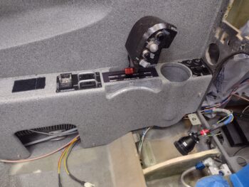
With the throttle quadrant out, and after adding Loctite thread locker and torquing the bolts that secure the throttle handle to the lever, I then spent some time dialing in the actual position of the throttle quadrant from the sidewall with the split and star washers in the mix. On my “final” (is it ever final?) install I also added Loctite to the threads of the long bolts that hold the throttle quadrant to the sidewall. These new additions required a tad bit more sanding and Dremel work for clearance to allow me to get the armrest into position without mandating the use of a 5-pound sledge hammer or tearing everything up.
My intention was to attach the throttle and mixture cables to the levers with the clevis and cotter pins, but after working over the armrest to jam it into place the first few times, I took a breather from any armrest removal or installation actions and simply focused on re-terminating the socketed wires back into the P4 CPC/circular connector (bottom right of pic) to get that buttoned back up.
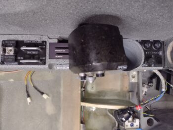
During my wire inventory of what wires needed to traverse the lower opening in the instrument panel bulkhead, behind the armrest front lower area, I realized that I had forgotten about a heat probe that will feed temperature data for the oil heat system duct air to be displayed on the EFIS. This temp probe is currently wired into the electrical harness that hangs off my Triparagon in my panel mockup inside the house. I found a rubber grommet that provided a snug airtight fit for the probe end and then drilled a hole in the top of the heat duct T-junction “gourd” and fit the grommet into place.
Now all that is left when I install the panel is to run the twisted pair of wires with the temp probe on the end of it, insert into the rubber grommet and add a little goop to the seam to hold it in place. Voila!
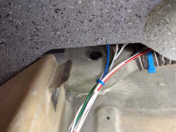
With the —once again— longer than expected shop shenanigans complete simply to finalize the install of the throttle quadrant, I then brought all my electrical kit back into the house to knock out the wiring of the RAM air can butterfly valve actuator switch (SW016). I’m fairly certain that this will be the last wiring endeavor I undertake until I work the instrument panel install (probably the canopy latch handle warning microswitch will be next, but that’s at least a few weeks out).
Since I will be installing the RAM air can butterfly valve actuator into the Hell Hole soon, I wanted to use its actual switch to control it during install and subsequent testing/ops. Thus, I made the wiring harness for this switch modular as well by using a 4-pin mini-Molex to allow me to mount the switch on the panel —after I’m done installing the RAM air can butterfly valve actuator— with a connector pigtail that I can then just connect behind the panel to the pre-wired (at that point) wiring harness integrated connector.
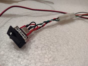
As with some of my oil heat valve actuator configurations, the RAM air can butterfly valve is actually closed when the actuator arm is fully extended and opened when the actuator arm is retracted.
Besides just ensuring it works, the main purpose that I’m bench testing this configuration is to verify the reporting signal wire position that will drive an AG6 warning annunciation and also a separate panel indicator regarding the RAM air can butterfly valve positioning [since I can’t easily pull altitude reporting data from the system, when the speed drops to a certain point (as in non-cruise speeds approaching an airport) it lets me know if my RAM air can valve is open]. The panel indicator is simply a “RAM Air Open” notification light.
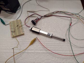
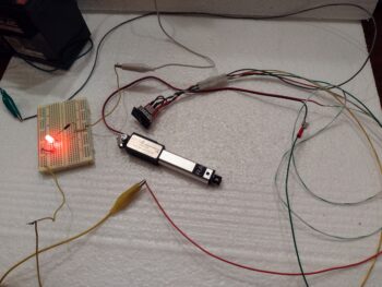
Here we have an LED representing the AG6 annunciator and panel indicator light to verify that the reporting signal is active when the RAM air can butterfly valve is open (actuator arm retracted). I’ll note that just a couple of weeks ago my wiring diagram showed all this being controlled via this actual switch, whereas now the RAM air can butterfly valve position reporting signal actually drives a DPDT relay.
Half the circuit on the relay is simply an “on when open” power feed to the RAM air panel indicator light. However, for the AG6 warning annunciation circuit, it comes via yet another relay that itself is controlled by an airspeed switch. Thus why I need to keep all these circuits and components straight in my electrical system documentation.
Speaking of keeping circuits and components straight and organized, I attempted to print off a slew of wire labels to find out yet once again that I was unable to complete the task since I’m low (now out) of label cartridges. I’ll order 2-3 more of those that I will need for this final push on the bird.
And with more inching toward the goal with tasks completed, I called it a night. Unfortunately tomorrow will NOT be a full build day, but I do plan on finalizing the throttle and mixture cable installs onto the throttle quadrant and get some preliminary work done on the GIB throttle quadrant.