
I started off this morning by knife trimming the wire routing hole that leads to the wing cable conduit on the outboard face of the extended & freshly glassed left wingtip.
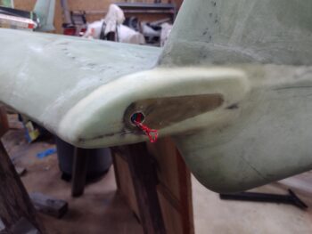
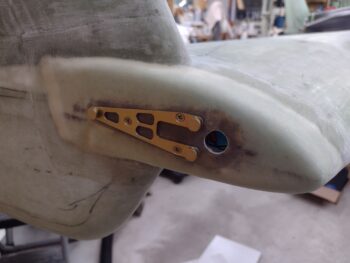
I then drilled and cleared out the Saran wrap in the three #6 screw holes that allowed me to mount the AeroLEDs Pulsar Nav/Strobe Light mounting bracket.
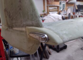
I then mounted the wingtip Nav light to check out how it looks… Personally, I love it!
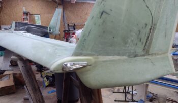
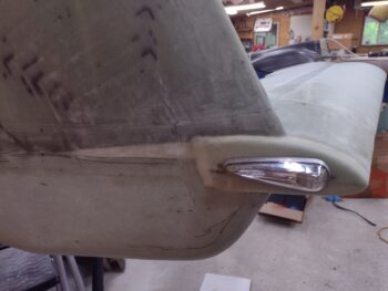
Side and angled shots of the left wingtip nav light.
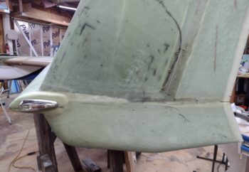
And a straight on shot of the left wingtip nav/strobe light.
I then repeated the same thing on the right wingtip. I’ll note that on each wingtip extension I spent a good 20 minutes on each side sanding and cleaning up the general area surfaces in prep for the upcoming micro finishing.
Here we have the wire access hole reopened and the nav light mounting bracket screwed in place.
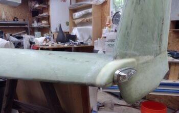
I then mounted the right wingtip nav/strobe light as you can see in these pics here.
And a shot from an aft angle.
And the requisite head-on shot of the right wingtip nav light.
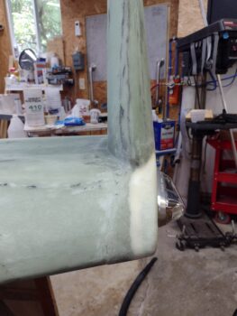
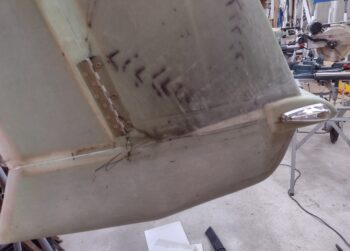
I then rolled into the assessment of my differing height elevations between the front of each respective wing where it meets the aft end of the CS spar/strake.
When I constructed my CS spar I followed the guidance of one of the old guard builders (who worked with/for Burt) that told me to shave a bit off the bottom & top of the CS spar at the outboard end to ensure it didn’t peek up above (or below) the wing… as in the end of the spar being thicker than the wing at that junction. This is to prevent having to pile on more micro either on the top, bottom, or both sides of the wing. Not a huge deal in the grand scheme of things, but it does save frustration and moreover, weight, if faced with that issue (apparently enough builders in the day were).
It wasn’t bad advice because even with the reduced thickness of my CS spar outboard end, I can see where even now it’s close to the thickness of the wing. However, as per usual in any mod we make, the toll must be payed to the induced law of unintended consequences… meaning the reduced thickness carried through somewhat down my spar… more so on the aft side.
Combine that with my intentionally getting anal on ensuring all corners of the wings matched the W.L.’s annotated in the plans, combined with my unintentional oops of setting the reference W.L. at 17.5 vs the plans 17.4 . . .
[again, not on purpose… I measured from the aft side of the spar where the spar cap dips about 0.07″ downward going aft vs the the front of the spar where it is level foam under the glass. This translated into a reference line closer to 17.5 vs 17.4 — which I of course didn’t catch until AFTER I mounted the wings and drilled all the wing bolt holes!]
. . . resulting in my wings setting about 0.1″ higher on my CS spar than they should be. If I had been a bit less anal and a lot more lazy, and strapped my wings to the CS spar so that they were even on both sides it would have resulted in a lot less work now! And of course most likely naturally much closer to the 17.4 W.L.
{sigh} I will say I think my wings are pretty darn straight [knock on wood!] and evenly mounted on the bird. When all is said and done they will look spot on… I just have to currently add a bit of filler to the aft end of the CS spar.
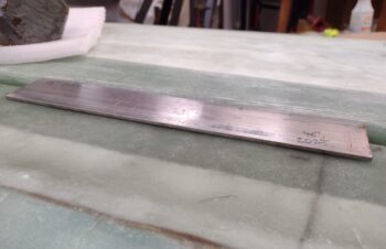
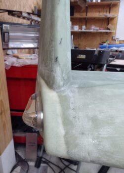
I’m about 1/8″ low on the left side, as you can see with the 1/8″ aluminum bar above. And I’m about 3/16″ low on average on the right side. This also has to do with the height of the “ridge” of flox and glassed joint where the top strake skin is attached to the front top corner of the CS spar…. obviously about 5-6″ forward of the aft spar edge. That spar/top skin joint ridge is a hair higher on the right side and is translating over into the increased measured depth of the required fill.
I was thinking of simply micro’ing on a piece of thinly cut foam, BUT because of how the thick spar cap UNI tape has little ridges at the end of every decreasing length, it creates minor dips and peaks on the spar cap area (at least on my bird). Yes micro is light, but epoxy ain’t so much… so instead of trying to fill all these inherent voids with micro, I decided to go with pour foam. I don’t care for a good amount of pour foam where it gets hit with constant sunlight, but this application will be thin and covered by a couple plies of glass —and painted white.
Thus, this is my current plan.
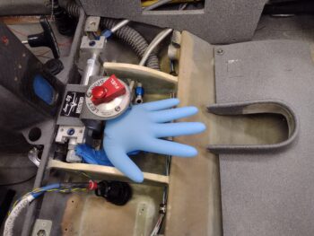
Finally, just a fun FYI: as I was measuring, assessing and planning my CS spar-to-wing shenanigans, I grabbed a shot of the left fuel tank pressure test blue glove… still inflated 2+ days later. I’d say we’re good on the left fuel and thigh support sump tanks.
I’ll note that I also spent a good half hour reviewing my notes and pondering the winglet-to-wing intersection fairing before doing a physical on-site assessment.
In addition, I’ll be discussing my revised plan for the exhaust pipes in the next day or two as well.
Pressing forward.