
As I pondered more on the cowlings and the exhaust pipes, I went ahead and engaged in the sideline gig today of knocking out the wingtip extension glassing —replete with internal nav light mounting backplate— for both the left and right wings.
I started by finalizing the shaping of each blue foam wingtip, in part “squaring” them up to ensure the outer face was vertical and parallel to the A/C centerline. This obviously puts the wingtip’s outer face at a different angle than the outboard surface of the upper & lower winglets.
I then marked a reference line that was essentially the chord of each wing… which for us would be W.L. 17.4. I started on the right wingtip by determining a good location for the nav/strobe light given it is a bit thick in height so it needed to come aft a bit (about an extra 1/4″) from where the original wire channel is so that the darn thing will fit on the wingtip.
The front of the light is about 2.25″ from the LE, so that puts the front edge of the blue foam wingtip addition’s wire channel at 2.5″ aft of the LE, versus 2″ on the original wingtip.
After getting fore & aft figured out on the nav light plate, I then simply center the front of the nav light on the wingtip center of mass, with the same amount of wingtip above and below the edges of the light.
The aft side the light was pointed along a line that was close to parallel to the wing chord, but at the same offset as the front of the light that needed to be centered. It turns out this is about 0.32″ or 5/16″.
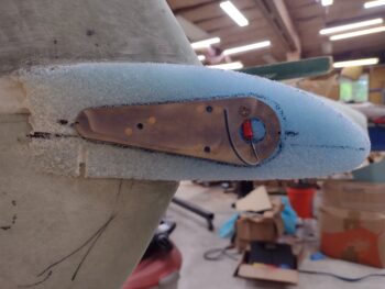
I then removed about 0.04″ of foam so that the backplate surface would sit flush with the outboard face of the wingtip foam extension.
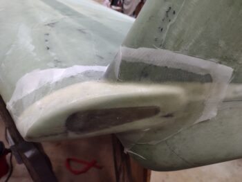
I then plugged the nutplate holes with Saran wrap and micro’d the nav light mounting backplate into place. I thickened up the extra micro and applied it in various spots to let it all firm up a bit before laying up the 2 plies of BID, as per plans.
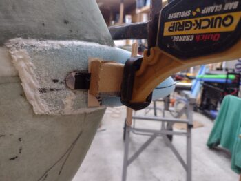
As you can see, to keep the backplate firmly in place I screwed a wood block to the wall and used it to keep my spreader clamp from slipping off the wall.
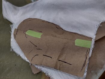
As the right wingtip’s micro’d-in-place nav light mounting backplate cured a bit, along with the added thick micro areas, I then took my rudimentary brown paper template I had made up and used it to cut 2 plies of BID from a large scrap piece.
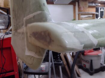
I prepregged the 2 plies of BID and wetted them out as I applied wet micro to the remaining blue foam of the wingtip extension. I then laid up the prepregged 2 plies of BID on the right wingtip.
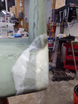
And then of course peel plied the layup.
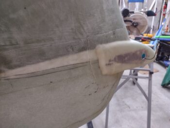
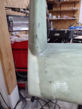
With the blue foam wingtip extension, where it gets thin as it goes aft it gets crusty and brittle and breaks apart more easily. I chipped all that away until I had solid foam and then just sanded it down and added a thick micro transition. I’ll sand this down and simply use micro during the finishing process to finalize the smooth transition all around the wingtip extension, but especially on this aft edge.
As you can see, I went with more of a traditional wingtip extension (‘ol skool?) where the outboard side of the winglet LE, for a good 4+ inches, sits on and transitions with the “wing” as it now appears with this extension. I did it this way to maintain both the vertical and horizontal components of each axis of the wingtip in keeping them parallel to the A/C centerline, and thus have a bit more of the nav/strobe light visible from the aft side.
A lot of my building buddies shaped this area so that only the inboard curve of the winglet appears on the wing top and the wing “ends” at the centerline of the winglet’s LE. That method looks awesome and is very clean looking, but it does require more of an angled mount for the nav light as the curve of the outboard winglet is carried forward so that the added wingtip extension front edge terminates very close (virtually nil) to the original wing LE when looking at it from above (vs my constant width extension).
Clearly there is no major safety or aerodynamic advantage one way or the other (that I’m aware of) and it is all just mainly stylistic preference.
I then started on the left wingtip.
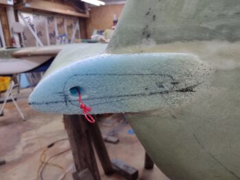
Here you can see more of the aft side foam —where it transitions into the winglet— is removed simply because I was mainly getting rid of foam that was breaking away at the thin points. I was also maintaining the vertical (parallel to vertical A/C CL) outboard wingtip face and this is in part due to that shaping as well.
Note that I had to create my wiring “conduit” hole at an angle going forward to the original wing wire channel… to allow enough meat on the front side of the hole when emplacing the nav light mounting backplate.
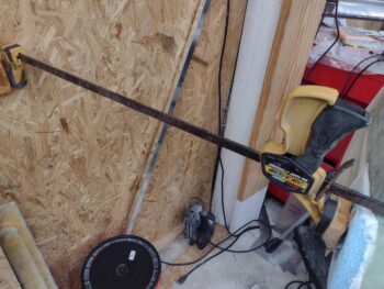
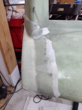
Since I didn’t have a solid surface to attach a spreader clamp, on the left side I simply used a long scrap of wood and a bunch of duct tape to secure the micro’d nav light mounting backplate into the blue foam wingtip extension.
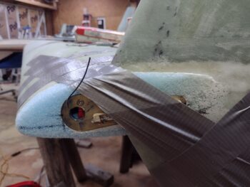
Here we have the nav light mounting backplate micro’d into the blue foam wingtip extension, as well as all the foam micro’d and surrounding glass surfaces wet with epoxy in prep for the 2-ply BID layup.
I used the same paper template for cutting out the 2 plies of BID as I did on the right wing (only off the big roll this time) and I also again prepregged the BID plies.
After laying up the left wingtip extension I then again added peel ply.
Another view of the glassed and peel plied left wingtip extension.
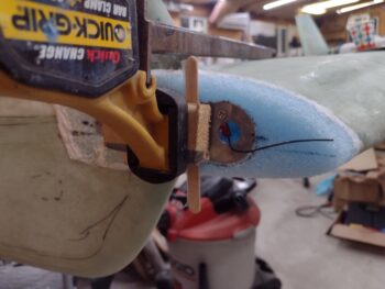
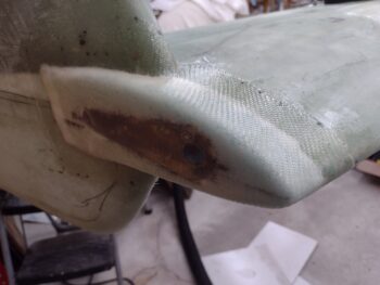
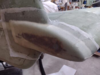
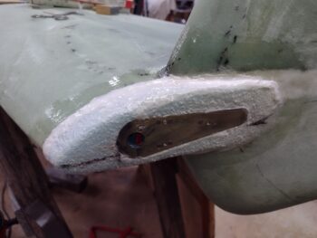
As the left side layup cured, I then pulled the peel ply from the right wingtip and cut away the glass over the wire channel in the embedded nav/strobe light mounting backplate.
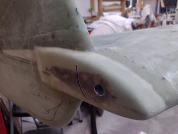
A parting shot of the glassed (aka FINISHED!) right wingtip.
Time for a glass of red and a late dinner!