
Today I continued on in my quest to get the exhaust pipes tweaked to fit inside the cowling… and still working specifically the left side at this point.
Before I could continue on with finalizing the configuration of the left side exhaust pipes, I needed to check the clearance between the spark plug in cylinder #1 with cylinder #3’s exhaust pipe.
I had Champion aircraft spark plugs installed but after a good bit of research during the past year I learned that Autolite 386 plugs are good to use with the PMag, so I picked a few up. Now I need to install them in the bottom plug holes in each cylinder to test out clearance with both the actual plugs I’ll be using and the PMag spark plug cables.
Now, not only are these Autolite 386 spark plugs 18mm [read: no adapter] and run well (according to a bunch of RV drivers… but can we trust them?? ha!), but they are pretty darn cheap to boot. That means I will be changing them out at every annual… which is where this exhaust pipe story has even yet another twist….
You see, I thought the tight cowling was causing all the issues, but interestingly enough when I went to remove the aircraft plugs on the right side, I couldn’t even get the socket over the plugs due to the exhaust spring tabs and springs being in the way. With some judicious bending of the forward cylinder’s exhaust tab I could force the socket on there and got the A/C plug removed. And yes, the Autolite plug was easier going in.
However, on the aft cylinder I had to remove the exhaust pipe completely to get my socket onto the A/C spark plug to remove it. I had a decent bit of oil oozing out of these cylinders, so I wasn’t mindful of replacing the aft cylinder exhaust pipe first to test out if the Autolite would have gone in easier than the A/C plug coming out.
I then took a few minutes to connect the PMag spark plug cables up to each respective plug and run all the cables forward to the front of the engine.
Ok, back to the exhaust pipes.
I had marked the left outboard exhaust pipe to allow me to secure the pipe to the 90° mounting flange, according to my index mark. After mounting all the pipes in place I then put the cowling back on.
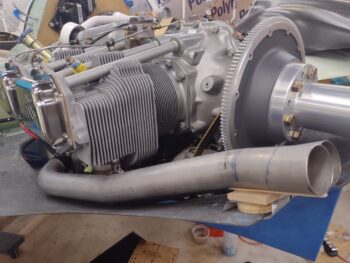
Here’s the left outboard exhaust close to the configuration where I plan to tack weld it in situ, and then have James finalize the job with a beautiful TIG weld worthy of 321 stainless steel!
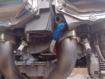
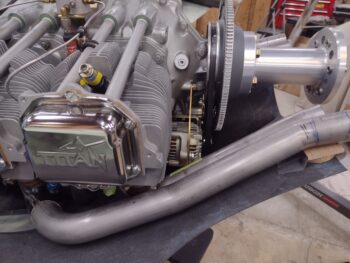
I then of course checked the clearance of the installed bottom spark plugs and their associated cables… much better than I had expected and not bad at all (I put green tape on the black spark plug cable boot to make it more visible).
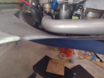
And here’s a shot of the clearance between the left outboard exhaust pipe and lower cowling. Optimized? Hell no!! But good enough for the space I have going on here! Especially since I’ll be lining the interior cowling with Thermo-Tec to keep it from burning up (as if I had a choice!)… I’ll also most likely get the pipes ceramic coated as well fairly early on to cut radiated heat down as much as possible.
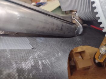
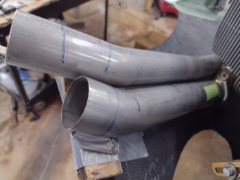
I then turned my attention to the inboard left exhaust pipe. Here’s the “dip” issue I pointed out yesterday. I used a ruler to show the dip more clearly.
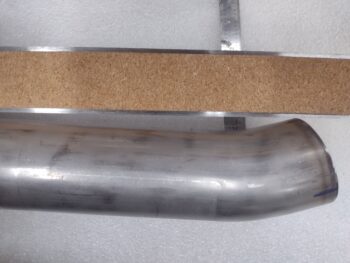
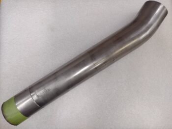
And here’s somewhat the same thing over on the bench… note the dip is very close to 1/4″ deep. Which is significant in this situation.
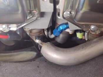
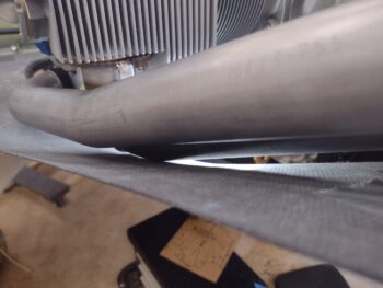
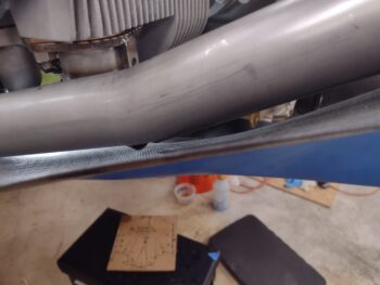
Back to the left inboard pipe set in place, here you can see that dip coming down and kissing the bottom cowling. Now, in reality that pipe is not touching the cowling. The issue is without a pipe used to lever over the spring loaded slip joint mount, it springs outboard a bit and messes up the mocking up of the pipe… so if it were all put together there would actually be daylight (albeit not much) under that dipped pipe.
I took measurements at the point where the forward curve (that causes the dip) starts on the left inboard exhaust pipe. I then set it in place and determined as best as I could the length of pipe (after trimming) that I would need to not only connect the pipe back into place, but to also ensure it stays nested with the outboard pipe.
My measurement was close to 1.8″ to remove the dip, so I planned on cutting off a 2.2″ replacement straight segment from the very aft end (which is excess and will get trimmed off all the pipes). The 0.4″ added difference as extra just in case [in retrospect it may still not be enough]. I then marked each cut line at each end with green tape.
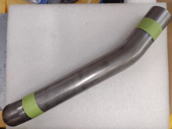
I then spent some time with my Dremel and small cut off tool to cut the pipe at the cut lines. I didn’t spend a lot of time on the green tape end since that will get trimmed to reconnect to the 90° pipe.
I then set it back in place… this isn’t a perfect representation since the added pipe is still a little high, but the low point now will be the 90° elbow and not the dip.
Moreover, with the hole in the cowl from me removing the goiter that was there for the alternator, I plan to expand my fill out a bit wider to add a hair more clearance depth to encompass that area of the low 90° elbow.
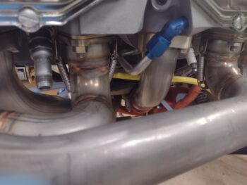
Here’s another shot of the left exhaust pipes mocked up in place. Note how you can now clearly see daylight underneath the majority of the pipes.
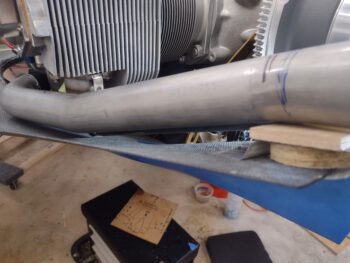
Another shot of the left exhaust pipes… I’m going to do my darnedest to keep the pipes nested together to optimize their flow.
Again, although set just a tad high, here is a good representation of the now straight inboard left exhaust pipe… sans dip. Much better as we can see above regarding clearance with the cowling.
Tomorrow I plan to break out the TIG welder and do some tacking on these pipes. After I lock in the position of the left outboard exhaust pipe then I’ll configure the inboard pipe and tack it up as well. Once the left side pipes are actually welded up and in place, then I’ll work the comparatively minor tweaks on the right pipes.