I have to say my schedule has been a bit wonky over the past few days. My friend needed to tend to some medical stuff, so I’ve spent a decent amount of time watching her daughter (aka my little buddy) and haven’t really been able to get back on the build until late this afternoon.
I will say that in the last few days I was able to get the engine flipped back upright, add some new oil and refresh all the top plugs and large drying tub with refreshed desiccant.
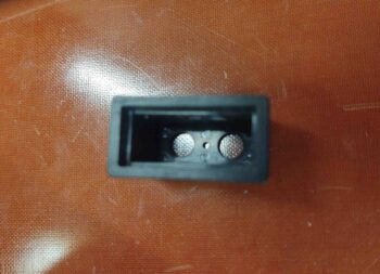
I’ve been working another sideline project here and there for the last few days as well: my dual-light Korey annunciator. I started off with a spare Korey Light back case:
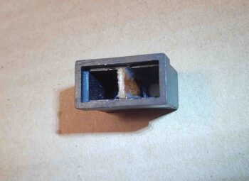
Then when I had some leftover flox I trimmed a 1/16″ thick piece of phenolic to fit inside of the Korey case and floxed it in place.
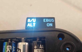
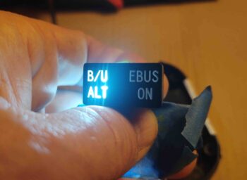
The floxed divided case sat in that state for a few days before I was able to find some decent LED lights to test it out. Here you can see a slight overflow of the light from the lit “B/U ALT” indicator slightly illuminating the “EBUS ON” side. I had suspected it might do this since the actual label faceplate is a piece of clear plastic that is painted black.
Since I was running about I forgot to grab any pics of my fix action, but I’ll describe as best possible:
I marked a line on the interior of the face place that mirrored the floxed-in-place divider piece. I then Dremeled a channel on the interior side of the face place, again aligned with the divider piece inside the back case. I then filled the freshly Dremeled channel with black gasket maker goop and let it cure for a couple of hours. It still wasn’t completely cured when I mounted the faceplate into the light back case. This squished the semi-cured gasket material onto the recently-added phenolic center divider:
A) preventing any light overflow from a gap between the divider and faceplate, and
B) minimizing any light travel through the actual clear faceplate from one side to the other.
My hypothesis regarding minimizing the light overflow proved correct, and I was very happy to have a successful test of the B/U ALT (“SD-8”) and EBUS ON Korey annunciator light.
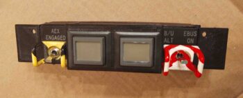
In addition, over the past 4-5 days I’ve been slowly taping off, painting and touching up the red candy stripes on the once white-only B/U ALT and EBUS ON switch guard. Sometimes you just gotta have fun and add a little bling to your build!
Currently I have 2 each x 10′ long RG-400 antenna cables in my possession. I know one was for my plan to place the Trig TT-22 transponder antenna out on the end of the right strake (I have it located in the nose now).
The other antenna cable was in response to info I received from the AeroLED guys on mounting their NAV/Strobe lights… and keeping the wing light wires away from any COM antenna leads. I thus planned on running a COM antenna lead to the engine side of the firewall through an aft able conduit via one of the aileron shear webs.
However, I’ve talked with a few guys at Rough River over the past few years who were running AeroLED NAV/Strobe lights and none of them had any noise or static issues. And nearly all of these were upgrade installs. With multiple reports of no noise issues, I decided to not make the build any more difficult than need be, and just run the COM antenna leads through the wing wire conduit as per plans.
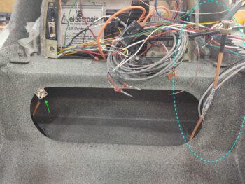
This did leave me with 2 antenna leads that couldn’t make it out the end the CS spar from behind the panel. Since I have permanently mounted 1″ diameter conduits from the respective outer spar faces to their interior CS spar bulkheads, I tested inserting and running BNC terminated antenna cables –both male and female– through the conduit while it had all the other wing light wires run through it as well.
BNC connector space wasn’t an issue at all, so I made a command decision to use what I had on hand and just run the RG-400 from the panel to just inside the CS spar GIB big oval access hole. I figured the fuselage is where the main antagonizers regarding antenna lead noise would be located anyway, so the RG-400 would be put to good use for the fuselage segment of the antenna runs since it’s clearly a bit better shielded than RG-58.
Speaking of RG-58, I’ll add about 3′ to the wing COM antenna leads and actually connect/disconnect them during wings ON/OFF ops from inside the plane, just outboard of the CS spar oval access hole.
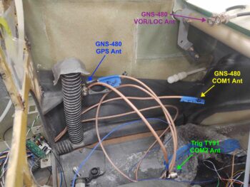
Here are all the COM and GNS-480 related antenna cables.
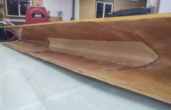
Tonight I finally got busy prepping the left side interior strake leading edge for install by measuring and cutting out a 4″ high by 50″ wide (the width of the fuel tank) ply of Kevlar. Since I’m using these prefab strake leading edges, I don’t have the foam and glass “crush zone” that the plans strakes do, so I’m adding a ply of Kevlar –covered by a ply of BID– on the interior leading edge, as well as a ply on the exterior leading edge. Although it adds a small bit of weight, it will give me piece of mind that my wet leading edge shouldn’t catastrophically come apart if I experience something along the lines of a bird strike.
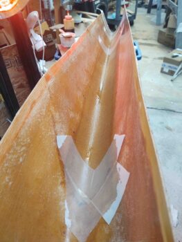
Here I’ve laid up the ply of Kevlar (actually 2 pieces overlapping) with a ply of BID over it. I didn’t prepreg these layups so this was a bit of practice in free handing decent sized layups.
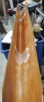
And another shot, a bit longer view . . .
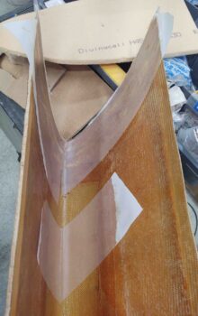
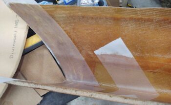
I also took the time to add a ply of BID to the end of the left strake leading edge structure to help repair/reattach all the slices I initially removed and then micro’d back into place. As you can see I peel plied this layup, as well as any points where the leading edge will intersect the front edges of the strake ribs.
Ok, tomorrow I do plan on continuing with the strake prep and build!
