
Today I started out by soldering in a glass fuse assembly onto the GIB Bose LEMO power wire. I would prefer to use an ATC blade inline fuse but the LEMO requires a 0.25 amp fuse, which are readily available in the glass version but not so much in the ATC blade fuse format.
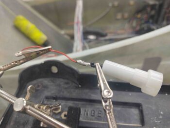
Once I soldered the wire I then covered it with red heat shrink.
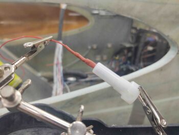
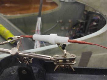
And then knocked out the other side.
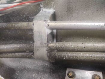
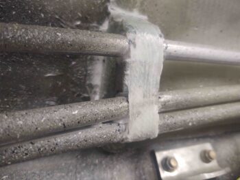
I then spent a bit of time measuring/cutting/shaping a foam bracket to add another securing hardpoint to the 3 fuel lines, all on the front seat right sidewall.
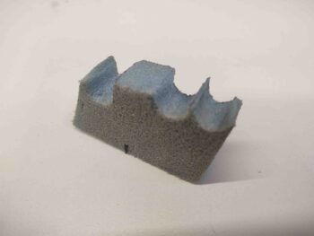
Fast forwarding a few hours, here’s the foam fuel line bracket secured with a 2-ply glass layup: 1 ply of UNI and 1 ply of BID. Yeah, it’s a bit rough, but it does the job. I did take a few minutes to clean up the potentially finger-snagging glass after I took these pics.
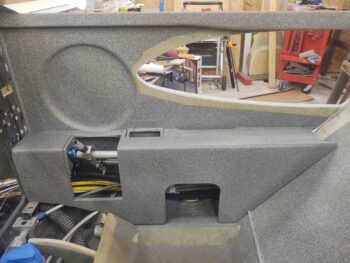
Along with the composite fuel line bracket —10″ upstream from the previous fuel line bracket located at the pilot seat bulkhead— I spent a few hours finalizing the wiring & cable management at the front seat right sidewall. This effort resulted in the right side fuselage cable runs complete from hell hole to instrument panel.
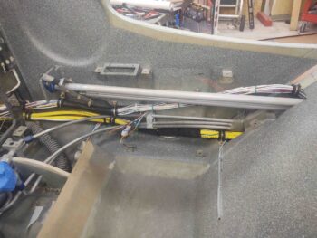
Here we have the installed ELT antenna with the actual antenna aerial set inside a painted 1/8″ Nylaflo tube. I had thought about hard-installing the ELT antenna inside the Nylaflo tube but decided against it. In this configuration this Nylaflo tube allows me to remove and install the ELT antenna when I need to, whereas if I had hard installed it I would have had to do major surgery to remove it if need be.
My final check was replacing the right front armrest to ensure clearance with the upper and lower wiring bundles.
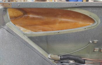
With the main centerline fuselage tasks out of the way, I then turned my sights on the final task of the evening: the left strake fuselage opening shaping and glassing.
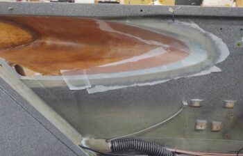
Here’s the before pic of the opening.
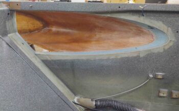
I then spent over an hour dialing in the shape of the sidewall to continue the angle of the left strake leading edge inboard to the inner edge of the fuselage sidewall.
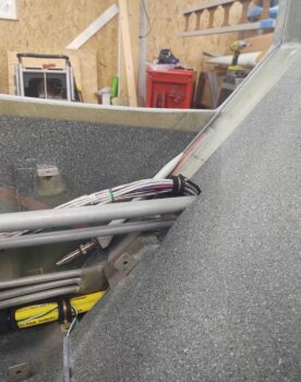
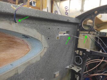
After I got the sidewall opening edge shaped, I then drilled a couple small holes to allow me to run a couple wire pairs from the aft side over the strake opening (for cockpit lighting) and a pair just forward of the canopy latch opening (for the canopy latch warning switch). Note the wires exiting the sidewall forward of the instrument panel.
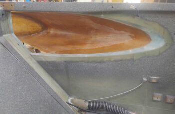
After I ran the sidewall wiring I then glassed the strake leading edge-to-fuselage sidewall intersection with 1 ply of BID. I then peel plied the layup.
Quite a few hours later I pulled the peel ply and did a quick cleanup of the layup.
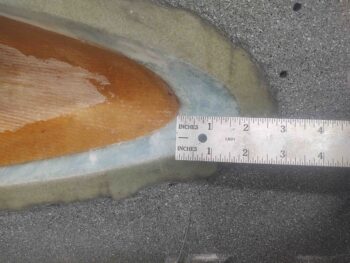
Out of curiosity I checked to see how far into the fuselage this continuing on of the strake leading edge intruded into the interior sidewall… almost 2″.
From here on out my next focus will be on installing the right strake leading edge.