Ok, so today I started working on Chapter 10 – Canard; Chapter 13 – Nose/Nose Gear; and Chapter 21 – Fuel system . . . due to an error in my glassing though, my Chapter 10 piece turned into a Chapter 22 – Electrical system piece . . . you’ll see below.
First, I’ll start with Chapter 13 where I removed the peel ply from the BC1 Battery Compartment struts (NG30 Extensions) & knife edged/sanded the edges.
Although I prepped some other layups first, for simplicity’s sake I’ll keep these all in order. I then glassed side B of each BC1 with a 2-ply BID layup & peel plied.
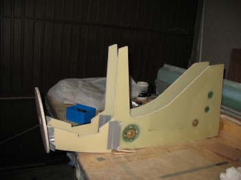
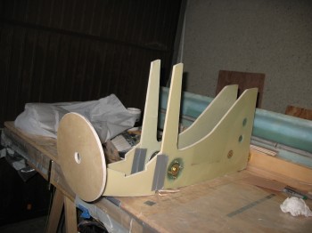
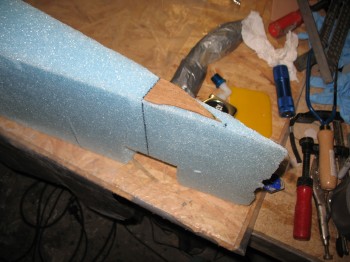
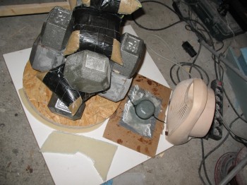
To jump ahead even further, here is the end result a few hours later after the BC1’s cured (I used fast hardener since the layups were small), the peel ply was pulled and the edges trimmed. I mocked up all the NG30 pieces–except for Napster, who was still in Time Out under the heater–to get an idea of how it all looked put together. Again, except for Napster, which gets mounted on the front of the NG30 vertical arms & aft of the BC1s, this below is the skeletal framework for the nose.
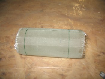
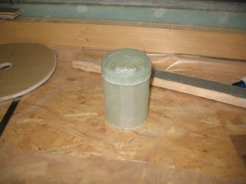
Now to Chapter 21 where I marked & cut the ragged ends off the fuel tank vent manifold body (that I glassed around a Rock Star energy drink can).
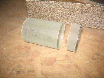
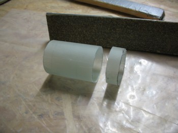
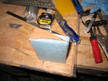
I then used one of the cut end pieces to make a form for the fuel vent manifold end cap using blue wing foam.
After I formed the shape I was looking for, I covered the entire form with duct tape & then fastened it using the tape to a duct tape base on a piece of cardboard.
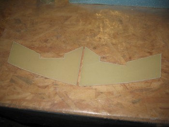
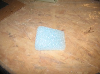
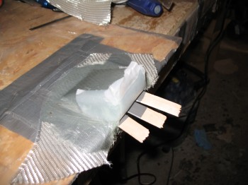
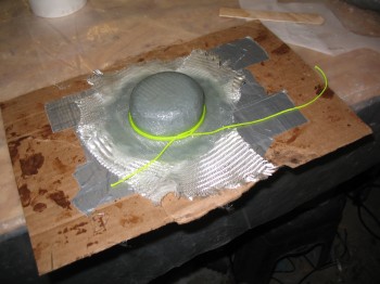
Now before I show any of the glassing on the fuel tank vent manifold, let me show what I was working on concurrent to this. I made a cardboard template of the shape of the canard next to the protruding antenna cables to make an antenna jack mount/cover for these cables, where they would tie into 2 respective jacks as a rather permanent fixture on the top aft/TE of the canard. I also shaped blue foam in an effort to make this jack mount/cover.
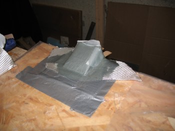
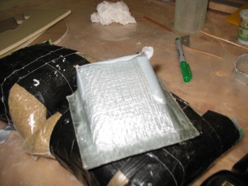
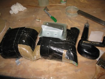
Here’s the resulting form to be glassed, shown first bare & then prepped with Duct tape:
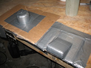
Now, in the pic above I clearly got tunnel vision and the requirement for the contoured bottom of the wedge shaped antenna jack/cover completely eluded me . . . temporarily. Of course once the glass was laid up & peel ply applied, I realized this was not in fact going to work for what I intended it to. Oh, well. I just lost a little bit of time, some scrap BID and a little bit of epoxy. In the end I got a piece that I think will work for the GIB’s headphone jack/cover.
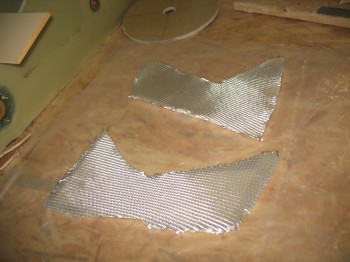
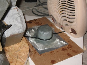
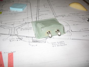
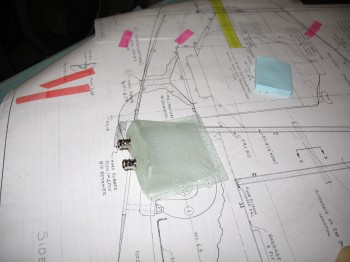
The following pics show the antenna/headphone jack being glassed:
And here they are curing in front of the heater (it was quite chilly weather in Germany even though it was late May).
Since I used all fast hardener on these components, I think the much faster curing sealed the glassed pieces to the foam more than usual. The first fuel tank vent manifold cap I made was a bear to get off the form, and I ended up tearing up the somewhat fragile foam form to get it off the darn thing. Thus, I had to make a completely new form for the second fuel tank vent manifold cap. No worries. Also, when I was glassing the 2-ply BID layup, some of the plies separated at the “corner” of the cap. Instead of messing around with pulling the separated ply, I simply added another ply of BID for 3-plies total on the second cap.
 After I got the second fuel tank vent manifold cap laid up & curing, I then mocked up the first cap to see how it fit. Once I saw that the fit was good I drilled a ~21/64″ hole (I had to use my Perma-Grit tool once I drilled the initial hole so the measurement is an approximate…forgive me Marco for not pulling out the calipers!) and mocked up the AN912 bushing & Nylaseal adapter.
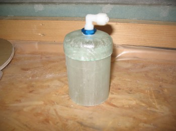 Once I confirmed that AN bushing fit well, I sanded/prepped around the hole on the cap and floxed the bushing into place.
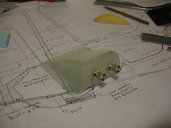
I then turned my attention back the soon-to-be headphone jack cover. First, I pulled it off its form & then drilled the holes for the antenna jacks. I then removed the peel ply.
I installed 2 antenna jacks (I’ll swap them out for headphone jacks) to test the fit. Of course everything is good except there is NO CONTOUR CURVE on the bottom of the jack cover to match the canard.
So this piece is definitely either a headphone jack cover or something else yet to be determined.