
I’ll start by apologizing again for my POS phone camera…. it annoys me that apparently the only thing it’s good for is selfies. But it’s all I have right now, so please bear with me as I bear with posting these crappy pics (that I often take 2-4 shots of and all are still slightly out of focus…. and yes, I’ve checked the settings many times!)
I started with a 1″ x 1″ angled steel bar that I had on hand. It had some surface rust but I was able to remove the majority of it. I then marked 4 x 1.5″ tabs on one end, drilled holes that would allow for a welded “hardpoint” between the flat intersecting pieces of metal being welded together, and cut the 4 x 1.5″ mounting tabs from the angled steel extrusion.
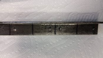
I then set the mounting tabs on the associated 1.5″ x 1.5″ angled steel main engine stand bracket cross pieces –top & bottom– to ensure I had them set in the right places.
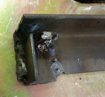
Now, as I mentioned during my TIG welding setup it’s been a couple of years since I’ve welded, but with both the high expense of Argon gas and my limited time I jumped right in. I knew there was Argon in the bottle, but it was low enough it wasn’t really registering well. In addition, the nifty little cheat sheet weld chart that Lincoln gives out during the EAA Tig Welding Workshop called for a 3/32″ Tungsten electrode for 1/8″ steel. I only had 1/16″ on hand.
Nonetheless, I trudged forward and laid down some appropriately crappy welds my first go at it. Towards the end of it I could tell I was definitely out of Argon gas, so with about 45 min left before the Gas shop closed I threw my empty tank in the truck and went on my quest to collect a fresh UBER EXPENSIVE ($90!!!) tank of Argon. [As a point of note, I ground and re-welded any of my initial welds that looked lacking in the strength department… with my limited time available, ugly welds here were acceptable as long as they were strong!]
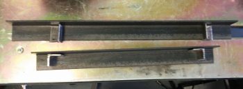
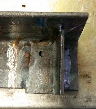
Upon returning back to the shop with a fresh full tank of Argon and some 3/32″ electrodes, this was what the other side welds looked like. Just a tad better I’d say… (yes, still not up to par with the gorgeous TIG welds we see on YouTube, but again, strength was what I was after here, not necessarily beautiful welds!).
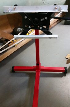
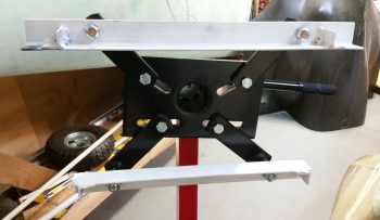
With the lower engine stand mounting bracket complete, I then started on the top bracket. Once I was finished with the top bracket, I spray painted both engine stand mounting brackets with the same fast drying white paint that I used on the engine mount.

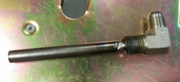
While the paint dried on engine stand mounting brackets, I then welded the 0.035″ walled 1/2″ 4031 steel tube inside the 1/2″ NPT x -8 AN oil heat 90° fitting. It took me a bit to rig it up so I had good access and a good welding angle, and I have to say I was going along beautifully for the first 75% of the circumference of the weld. I had to reposition the setup and I had only one little bit to go on the final weld when I slightly dipped the electrode into the puddle. Well, with so little to go I trudged forward to finish it. Mistake.
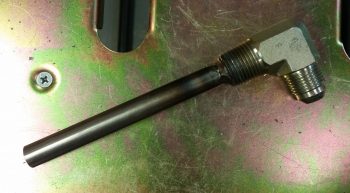
Within about 2 seconds of dipping the electrode into the puddle –with my trying to concentrate on the thicker fitting’s base metal (I tend to go high on internal corner welds)– I blew about a centimeter diameter hole in the thinner walled tubing. Since I had to buy a foot of this stuff, I ended up simply cutting a patch out for the hole from the other end of the tube. I then prepped the patch piece and the hole area, and tacked it into place.
I ran some water through the tube to see if the patch worked, but I have a couple of leaking spots that I’ll need to do some touchup spot welds after I return from NC. For now this is good, and I cut the 4130 tube at my calculated 4.4″ long (high actually).
I then ran out for a final going away dinner for buddy Greg since in reality this is the last time I’ll see him in quite a while.
When I returned, the quick dry paint had cured. I then determined the best bolt hole locations for my configuration and drilled out the 1/2″ holes that allowed me to bolt the respective engine stand mounting brackets to the beefy engine mounting arms.
Here’s a closer shot.
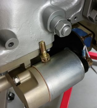
With the engine mount ready to go, I then unmounted the engine from the fuselage. I took this pic because I would often bump the engine and the starter bolt that I had setting in this location would fall off onto the shop floor. However, it stayed right in its spot the whole time I removed the engine from the fuselage, so the operation must have gone fairly smoothly . . . both literally and figuratively.
Since I needed to make a decent amount of noise and do some grinding and drilling on the engine stand mounting brackets to get them mounted to the engine mount, I called it a night.