Chapter 13/16/22 – Straying off course

I started off today pulling the peel ply and cleaning up the layups both on the underside “nose bridge” and the fuselage corners just forward of the canard LE.

I then set the canard in place to test the fit and look of the new “fuselage corners.”  I think these will work!

A shot of the whole shebang from a canard surface view.

I then wondered off my assigned heading a bit with an impromptu arts and crafts project. Sometimes that wild hair just gets you, and today it was labeling the control stick.  It ended up being over a 3 hour detour (whoops!).

I already had a few labels on it just to test out the label size and attachment, and with these labels on a few years (grant it, not under constant operational use) I figured I would charge ahead with the rest of the labeling.  So I’m calling this labeling Round 2.

I had two issues with the round 2 labeling, one minor, one major.  The minor issue was the font size was a little too big in a lot of areas and made it look a bit gaudy to me.

The more major, critical issue was that I sent the pics of my control stick round 2 labeling shenanigans to Marco.  Critical mistake! ha (Just kiddin’….) With him being a professional pilot, I was quickly informed that airline standardization would have the autopilot disconnect on the side where my temp warning defeat button (black) was currently located.  Moreover, the button should be red.  This latter recommendation was on my to-do list anyway, but I really do appreciate Marco’s input, since he’s been involved with a lot of human factors training with the airlines and I want to be as safe as possible (thanks again Bro!).

Thus I tweaked my labeling yet again, primarily swapping the autopilot disconnect with the temp warning defeat button.  I also took this opportunity to replace a bunch of labels with the smaller font.  I really do think it helps reduce the gaudiness of the stick.

A bit later when I went back into the house, I dug around and found my Infinity Aerospace box and grabbed a red and gray button to swap out.

This is the final mod (so far) that I made on the control stick:

I then got back to work on the nose.  I made up a test nose hatch door latch striker and mount to dial in the nose hatch door latch.  I simply used Gorilla duct tape to hold it temporarily in place.

After a few iterations of finding the correct interface, height, alignment, etc. between the striker and the latch, I made up a couple phenolic nutplate assemblies with K1000-3 nutplates and floxed them into a 3/8″ piece of scrap Devinycell foam to make up the nose hatch latch mounting plate.

About an hour later I filled the nutplate threads with Saran wrap, made a 5/16″ hole in the lower right (left, looking at pic) for a flox hardpoint [for cable-securing adel clamp], and then 5-min glued (+ flox) the top edge of the mounting plate to the underside aft lip of the nose hatch.

When the 5-min glue was nice and cured, I then laid up 2 plies of BID on the front face . . . (sorry for the fuzzy pic)

And 3 plies of BID on the aft face.

Here’s my attempt at getting a shot to show the black marks on the latch mounting plate with the nose centerline… at least the pic of the latch mounting plate is clear here.

And with that, I closed up shop to the let these layups cure overnight.

I then went in the house and spent about 20 minutes annotating the control stick switch circuit changes on my wiring diagrams.


Chapter 13/22 – Gravity defying foam

I started out today by spending nearly an hour updating a few electrical diagrams and printing an updated consolidated switch diagram.

I also went on the hunt –and found– a toggle switch to replace the rocker switch I had previously identified for the Tach Source Select switch (SW005) –the rocker being a bit too robust to fit on the panel.  “Luckily,” I have a lot of spare switches on hand from all my different starts and stops in my journey on my electrical system.  I labeled the new switch and pressed it into service.

I have 5 mini-toggle switches on my panel, this one being the latest addition.  My final prep work on the panel is simply drilling the keyways for these mini-toggles on the back face of the panel.

The panel’s big toggle switches, all from B&C, are situated with their keyways on the top. Luckily I decided to tone these switches out with continuity checks to see which direction was ON and OFF, so that I could set the keyways appropriately: these mini-toggles happen to install with the keyways DOWN, opposite their bigger cousins.  I also knocked out drilling the holes for the keyways on the 3 AC System switches at the bottom of the center strut.

Which look like this on the front side:

I have one more mini-toggle keyway to install for the Autopilot source select switch, but since it’s currently hardwired into the panel mockup, I’m waiting until I tear that apart to drill the keyway.

My immediate goal is to get the nose hatch door latch installed, but before I can move forward with that I needed to finish glassing the underside of what I call the “nose bridge,” or the area in-between the nose hatch and the canard mounting opening, which is covered by the aft nose/avionics cover.

With different nose build ops having been done in this area involving microing in blue foam inserts, etc. there was a fair amount of cured micro blobs, mini-stalactites if you will, that were all along the seams of the blue foam under this area of the nose.  In addition, the first couple of inches from the edge of the nose hatch going aft were shaped and glassed with a couple of plies of BID…. so a lot to get organized and glassed under this one little strip of nose.

I chipped, pried and cracked off the offending dead micro blobs, which then left me with some pretty nice divots along along the bottom surface of the “nose bridge.”  Looked like the surface of a moon pummeled by asteroids… you get the picture.  Clearly I needed to resurface this area before glassing, but gravity was kind of getting in the way for pour foam, and I wasn’t quite ready to invert my fuselage just for this one task.

So I decided to let the expanding pour foam do most of the heavy lifting, and I would merely provide a surface and some constricted space for it to work its magic.  I took some thin cardboard, covered it with duct tape and then taped the front edge tightly to the existing glass.  I also taped each side simply to keep the liquid pour foam from flowing out each end since the sides are lower than the middle section.

I then whipped up some pour foam, slathered it against the underside “nose bridge” foam surface as best I could and also on the surface of the taped cardboard.  Once all the foam was out of my mixing cup I simply pushed the cardboard up a bit and taped it in place.

Voila! The pour foam expanded into and adhered itself into the crevices of the blue foam on the underside of the “nose bridge” and did exactly what I had hoped it would.

With the nose bridge ready for shaping and eventual glass, I then got busy on filling in the gap of the fuselage sidewall just forward and slightly below the canard leading edge.  I taped off the canard on each side with clear packing tape, then used gray duct tape as a dam (aka form) both for the interior and exterior wall.

Here we have the right side ready to go just like the left side.

I then whipped up another batch of foam and poured it into the fuselage sidewall duct tape forms I had made.

And got the results I wanted here as well.

A little bit later I had trimmed and sanded down each fuselage sidewall to look like this.

And was still dialing in and shaping the foam for the “nose bridge.”

Getting much closer  . . . at this point I removed the canard.

It may not look like it, especially with the glass laid up, but I did a lot of sanding both on the foam and the existing sidewalls in prep for new glass.

Here’s a shot from inside the nose hatch looking aft.  You can see the existing glass across the front part of the “nose bridge” that makes up the lip of the nose hatch.

I used the rest of my thin cardboard to make up a template to cut the 2 plies of BID I was going to layup on the underside of the “nose bridge.”

Using a slightly too small piece of plastic, I then prepregged the 2 plies of BID.

I then laid up the BID on the underside of the nose bridge.

A shot of the new foam with 2 piles of BID laid up.

After peel plying the “nose bridge” layup, I then laid up a ply of BID on each of the freshly pour-foamed canard LE-fuselage corners.  I then peel plied those layups as well.

After I clean up these layups tomorrow I then plan on getting onto installing the nose hatch latch, etc.


Chapter 13 – Nose paint & more!

After I posted last night’s blog post I went back to an email my buddy Dave Berenholtz sent me that contained a bunch of good info that he compiled regarding instrument panel labeling.  The boiled down info is that there are essentially 4 accepted fonts (and their differing variants) for panels: Helvetica, Futura, Arial and Franklin Gothic… the first 2 used by NASA.

I played around with Helvetica and Futura for a bit, and then tried out what some of the bubbas on the VANs Air Force forum recommended: Arial and Franklin Gothic.  The VAF info also recommended 12 pitch font.  I noted Franklin Gothic looked better not bolded, but the size seemed smaller than the others so I bumped it up to 13 pitch.  I played around a bit more with all of them, but I kept coming back to Franklin Gothic as my label of choice.  And also un-bolded at 13 pitch.  I printed out a quick sheet and cut up the labels just to check font size.  I’m really liking what I’m seeing so I plan on sticking with this one (thanks for the info Dave, very helpful!).

I went out to the shop and decided to quickly knock out rounding the corners on the nose hatch door hinge tabs.  I marked the radius using an AN970 washer.

And then trimmed the corners with the Fein saw.  I then hit each corner with the sanding block and called this task good.

I had to run out to an auto parts store to finally get the correct color trunk paint for the interior nose.  Upon returning, I pulled the fuselage out in front of the shop.  Luckily it was another nice warm day.

Here’s the nose interior a bit later.  Although the front battery compartment and the NG30 area compartment are painted 2 different colors, unless we’re getting really technical they look pretty darn close to the same.  I finished up with hitting both compartments with a couple coats of matte clear coat in the upper areas where tools or hands might rub against or ding the sidewalls.

I then mounted the canard.  I have to say I was pleased that all the bolts went in without much fuss.

As a point of note, this is the first time the canard has been installed on the plane since the upper nose and canopy are in place.

I then set the aft nose/avionics cover in place and got to work dialing it in to fit over the canard.

Here we have the untrimmed, unaltered aft nose/avionics cover.

You can see from the front there is quite a large gap.

Here are the successive rounds of trimming I did.  The pics below show 5 rounds, but I missed one set of pics, so it was actually 6 total rounds of trimming with the Fein saw.

I ran out to grab a quick bite to eat, and when I returned I dialed in the rest of the aft nose/avionics cover fit onto the canard pretty much by hand.  After another half hour I was very close.

The following are just a bunch of pics of the canard installed for the first time with the nose, aft nose/avionics cover, and canopy all in place.

A side profile shot.

A couple more shots.

Some head-on nose shots.

A closer in shot…

And a couple shots with the nose hatch open:

Tomorrow I’ll start working the nose hatch door latch in earnest, and the aft nose/avionics cover attachment points as well.


Chapter 12/13/22 – Going 2-tone!

I started out this morning with what I typically start with during the build: a cup of coffee as I write out or finalize my day’s To-Do list.

Well, I had just finished my To-Do list and started work on the panel, which was in the house (important detail).  I dialed in the GNS-480 GPS so that it fit in the panel, and then I drilled the screw mounting holes for the HXr EFIS (#6 screws) and the Mini-X EFIS (#4 screws).  I was remiss in mentioning this on my task list for the panel on yesterday’s blog.

It’s been a bit chilly the last few days here as we move into Fall, so when I went outside to head for the shop I realized that it was a very nice warm day.  A day, perfect for??  . . . painting!

So my To-Do list almost instantaneously vaporized into thin air as the new task was to get the nose area internal painting finalized.

My first actual shop task was cutting, sanding and cleaning up the 1-ply BID layup in each channel on each side of the nose hatch door hinge bracket mount.

I then spent about 45 minutes prepping the nose area for paint.  I clearly didn’t want any paint getting up into the cockpit or on the canopy.

I started out with some primer on the unpainted surfaces.  And then that’s when the proverbial NO-GO hammer fell.

So about a month ago I picked up some Trunk paint from a local auto parts store, the same paint I used previously to paint the avionics bay area, nose wheel well cover, etc. However, when I started painting today, it had a noticeably green tinge to it.  I then realized that if you looked very closely at the cap (and read the small label on the back!) it was black with aqua speckles.  I didn’t realize, or expect, that that was a common color for trunks… but it wasn’t going to do for my nose paint.

Oh, hold on boys and girls, the story gets better.  Well, I told my friend’s daughter, my little buddy, that I’d hang out tonight.  My painting window had passed, so on the way over to their house I stopped off at an open auto parts store… no joy on any of the right paint.

Then, on the way back home I checked WalMart, which was open later.  Not the same brand, but it looked like the same color paint: black with gray speckles.  Ok, so I bought it.

Determined to get this paint laid down tonight to cure (so I can get on with the nose build!), I pulled the fuselage out of the shop and set up some extra lights.  I shook the can up, did a test shot in the air, and then started spraying.  After a number of strokes I realized something wasn’t right . . . wouldn’t you know —NO KIDDING— someone switched the caps!  This was not black with gray specks, it was a metal gray with black specks.

And now I’m in a real pickle: unlike the black with aqua, I really like this color!  Plus, I’ve got the fuselage out in front of the shop with all the lights set up… So I said, “Screw it, I’m going 2-tone!” (meaning the battery compartment will get a different color of paint).  I was getting something DONE tonight!

So here it is . . . in all of its semi-glory! (To be clear, I’m not looking for perfection on this internal nose paint stuff, just cleaning up all the disparate foam colors and glass mismatches).  BTW, from Napster aft will be the original black with gray specks.

One thing I didn’t show last night was I actually popped the canard onto the fuselage to check out the fit and look with the upper nose completed. I quickly realized that when I had last installed the canard, the top nose area around the front end of the longerons was much fatter.  With the new trimmed F28 outboard edges, it made the canard upper mounting tabs a bit wide on the outboard side.  I marked the mounting tabs and then removed the canard.

Well, in my fervent quest to get yet one more thing off the To-Do list tonight, I grabbed my coping saw and trimmed down the outboard excess on the upper canard mounting tabs. I’ll certainly have some sanding to do to finalize the shape and fit, but the major lifting on getting these to shape is done.

Tomorrow I plan on finalizing the interior nose painting and then moving on to the nose hatch latch and the aft nose and avionics cover install.


Chapter 13/22 – Command Decision

I started off today laying up a ply of BID on each side of the nose hatch hinge bracket mount in the hinge channels.  I sanded the channels down first, then dug out some of the blue foam on the sides to then add micro and flox for essentially a flox corner.  The ply of BID basically covered the channel outboard walls, the front (bulkhead) part of the channel, the top (nose underside), and then overlapped onto the inboard side of the channel (the protruding hinge bracket mount).

I then did a number of shop tasks not really worth mentioning, before I was then able to work on the instrument panel.  I also did a myriad of measuring, fitting and planning for installing the nose hatch door latch and latch hook.

In contrast, a very worthy point of note on the instrument panel is my command decision to move the planned location of the Master switch, Ignition #1 (ElectroAir) and Ignition #2 (P-Mag) from a plate that would have been just forward of the control stick, onto the lower right corner of the panel.  After thinking about it for a few days, I just decided that a switch plate forward of the control stick on the side console would just be too much hassle.  The more I thought about it the more I liked the idea of having these switches on the panel: they seem to flow better and the fit is more natural.

A number of hours later, after working on a bunch of other panel tasks, I finally got around to marking up the panel in ‘ol skool fashion for the Master and ignition switches.

After drilling the master and ignition switch holes, I then used my 3D printed large switch template for drilling keyways on the back side of the panel.  I actually drilled the keyways for every large switch on my panel (6 total).

Here I’ve marked the keyway location . . .

And then carefully drilled it out.  You want to get deep enough (around ~1/16″) so that the keyway will sit flat on the panel with the key in the hole, but obviously NOT drill all the way through the panel and have a nice hole where you don’t need one.

I then reassembled the panel…. this is post welding, so there are a number of areas that I tweaked and repaired by welding the holes in (as in the upper right CAMLOC) or just making them smaller.

Note the 2 holes below the vertical card compass that provide access to the adjustment screws.  Also note the 2 dimmer switches on the center strut are installed.

About the only tasks left to do on the panel, besides actually installing it, are fitting the Garmin GNS-480 GPS and drilling the keyways for the small switches.

Pressing on!


Chapter 13 – Nose hatch door install

I started off today simply prepping and then laying up 1 ply of BID on the left hinge tab on the nose hatch door.

I did some workshop housekeeping chores, pulled the canard from the rec room in the main house and placed it in the shop, and also did a bit of welding on the instrument panel.

A bit later –after the above layup cured– I got back to work on the nose hatch door install.  Here’s a video recapping all the pertinent points.

Tomorrow I’ll press forward on the nose components.

Chapter 13 – Nose is alive

I started off today checking my floxed-in-place nose hatch door hinge tabs… they cured nicely and kept their alignment.

With the tabs good I then laid up 2 plies of BID on the interior tab walls overlapping onto the underside face of the nose hatch door.  Normally I would use simple BID tapes here, but I went all the way across since I’ll be laying up glass over this and wanted the transition as clean as possible… and at 3″ apart, we’re only talking a 1″ x 4″ added strip.

While the layup above cured, I got busy working on the 6061 aluminum “bungs” that I’ll weld to the exterior side of the hinges to keep the nose hatch door securing pins more secure, and more aligned.

What I needed/wanted was essentially a 5/16″ ID tube with a at least 0.090″ wall thickness.  So a 1/2″ OD tube with a 5/16″ ID would have worked great… IF I had it on hand.  Which I didn’t.  Thus my lathe work.

I started out by center drilling a length of 1/2″ dia. 6061 rod.

I then drilled out the center to 5/16″ to a depth of about 1 inch.

I then test fitted my aircraft grade hinge pins.

I didn’t get pics of the remaining process, which was fairly easy.  I just lopped off the nubs on the horizontal bandsaw and then faced the end(s) to length, which is 0.322″.

And Voila!  Here they are.  The fit is nice and tight on the hinge pins.  The gap between each bung and the top flange of each pin allows for the combined thickness of the hinge and the hinge tab.

I then cleaned up the nose hatch door hinge crossbar securing clip.  I rounded the aft side of the tab part that will get secured to the underside of the nose hatch door.

Here’s a side view, albeit a bit blurry.

And a shot with a test 1/2″ bar inserted into the clip.  This bar is the same diameter as the crossbar at the aft end of the hinges.

I then installed the clip on the hinge crossbar.

It fit well, so I pressed forward with my nose hatch hinge install plan.

By this point the inboard layup on the nose hatch hinge tabs had cured.  I pulled the peel ply and cleaned up the overhanging glass.

I then used clamps to position and hold the nose hatch door to the hinges.

And test the operational geometry of the nose hatch door and hinges… which I’m happy to report was excellent!  (Again, a big shout out to Mike Toomey for his advice on the hinges!)

I then 5 min glued the hinge clip tab to the underside hatch door surface and the tube part of the clip to the top (as situated here) of the nose door hinge tabs (I had previously cut circular notches to match the OD of the tube part of the clip).

I gave the “5 minute” glue a full hour to cure while I engaged in other shop shenanigans. About every 10 minutes I would cycle the door from open to closed, and vice versa, to ensure that the pivot geometry and alignment was still good.

I then removed the nose hatch door with the hinge crossbar clip secured in place via 5 min glue.

I then did 3 layups: starting first with a ply of BID over the hinge crossbar clip’s aft semi-circular tab.

Next I laid up 1 ply of BID on the outboard right hinge tab (top in pic).

Lastly, I filled in the narrow gap beneath the hinge crossbar clip aft semi-circular tab with a a mixture of wet flocro.  Then on the front corner at the junction of the exterior clip tube and the nose hatch door surface I created a fairly large flox fillet.  I then glassed in 2 plies of BID from the clip tube near the top and overlapping forward onto the nose hatch door (onto the previous inboard 2-ply layup between the hinge tabs).

I employed the thick heavy nail again to weigh down the peel ply and keep the glass on the top of the clip tube pressed against it.

I then closed up shop for the night and left these layups to cure.

Chapter 13 – Nose hinge tabs

Today was all about progressing on the nose hatch hinges.

I started by spending a good hour setting up and adding 3 plies of BID to the nose hatch door attach clip. I cut a drinking straw lengthways and curled it up tighter, taped it and then used that as a lip on the front, top edge of the “C” to have a radiused entry for the hinge assemblies front tube to press against when this clip is being snapped into place. The straw contraption is being held by the clothespins with a big nail to push the glass down behind the straw to make it tight, and give the lip more of a protrusion.  You can see the peel ply on all the external surfaces.

I then got busy on the actual nose hatch door.  I first spent a good half hour cleaning the old sticky duct tape off the exterior surface of the nose hatch door, and the nose just above the hatch.

Then, peeking up through the taxi light opening, I set the door in place and then used a few previous dots to slowly dial in the inside lines of each hinge.  I didn’t have a way to reach up in there to simply mark the lines, nor did I have a good angle to do so really with an extended pen contraption (I was leaning this way), so I simply took my time (~30 min) and slowly dialed in and marked the lines along the inboard edge of each hinge (left pic, below).

I then used the Fein saw to cut the slots into the interior side of the nose hatch door (right pic, below).

With the slots ready to go, I then cut the first hinge attach tab out of 1/16″ thick G10. I made these tabs a bit taller/deeper than they will most likely end up being, simply to make it as easy as possible when attaching the hinges to these nose hatch door hinge tabs. Of course I’ll trim them to final depth & shape when the hinges are attached.

I then sanded both sides of the G10 nose hatch door hinge tab.

I then cut the second nose hatch door hinge tab and sanded it as well.

Here we have the pair of nose hatch door hinge tabs test fitted into the nose hatch door. They fit great, so time to mount them.

I mixed up some flox and slathered a bunch of it into each slot. I then slid the nose hatch door hinge tabs into place until they bottomed out.  I clamped the taped hinge assembly to the hinge tabs to ensure that they were vertical and matched the hinge they would be attached to.

I was heading out to grab a quick bite to eat, so I placed my 5# sledge hammer on top of the hinge tabs to ensure they stayed seated fully in each slot.

I then left these nose hatch door components to cure overnight.


Chapter 18/22 – Canopy complete

Yep, I’m calling the canopy done.

The latch handle still needs to be dialed in and the SC-1 needs to be permanently mounted (I’ve ID’d bolts in an order I’m compiling with ACS), but besides those the only thing that needs to be done is to finish & paint the outside of the canopy.  I’m calling that Chapter 25 since the rest of the exterior will need to be finished as well.

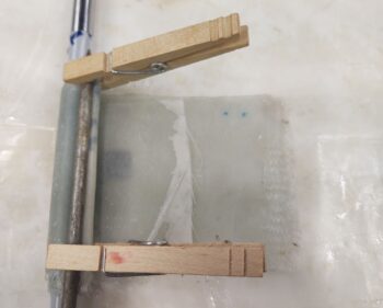
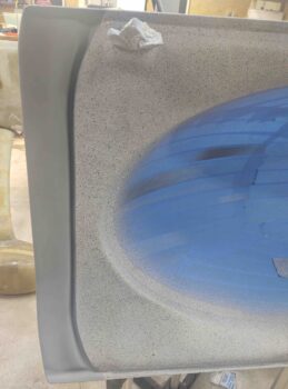
I set out to make my first task of the day to clear coat the interior canopy frame that I painted last night.  Well, I lightly sanded the area where the EXPERIMENTAL label was getting attached to… to knock down some of the bumps of this granite paint, and literally went one stroke too far and cut though the top coat of paint and bared a couple bigger spots of the light gray primer beneath.

I was none too happy, but this granite paint takes at least a good 2-3 hours minimum to dry, especially before clear coating.  So I touched it up with a very light blast from the can and let it sit.  I then worked on the instrument panel for almost 4 hours (see end of post).

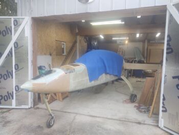
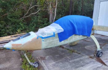
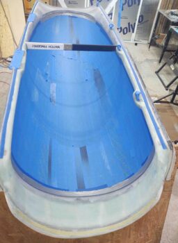
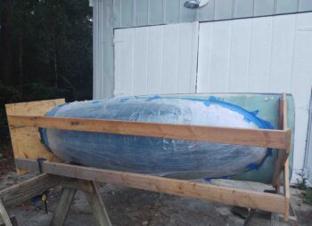
Late in the afternoon I finally got the canopy out in front of the shop.  Thankfully the weather held and there was no rain.

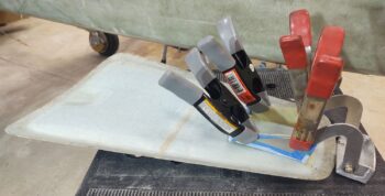
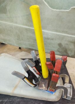
The first coat of clear was a light one, as per the instructions.  The 2nd and 3rd coats were medium.  I then hit it with a 4th coat in the “high traffic” areas, and let it sit for a couple of hours to cure.

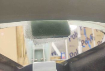
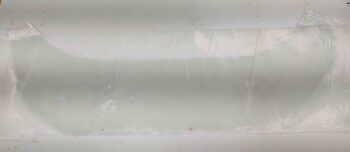
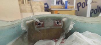
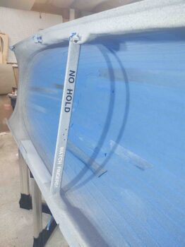
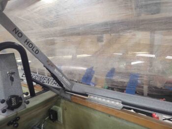
Back in the shop a few hours later I removed the protective tape and cleaned up the canopy edge glass (there was some glue gunk in spots from the tape).  I also added the EXPERIMENTAL label on the hinge side of the canopy frame.

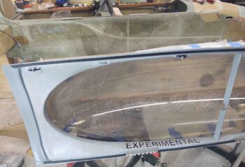
Yes, black and white is the color scheme for labels on this canopy…

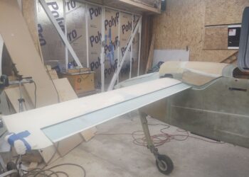
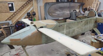
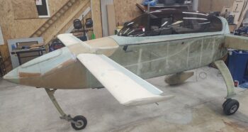
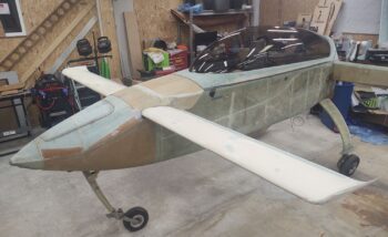
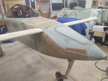
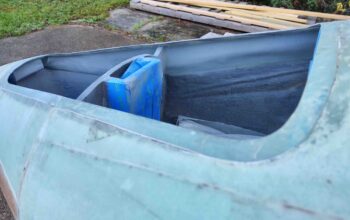
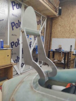
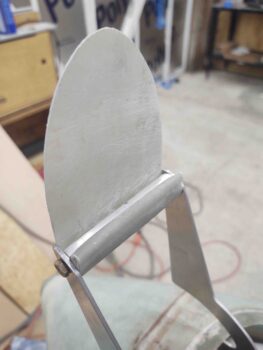
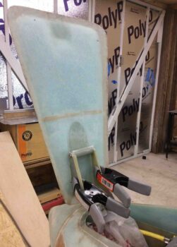
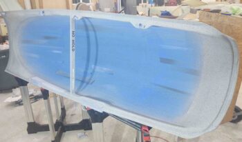
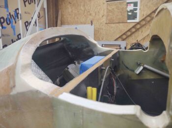
I then installed the canopy back onto the fuselage.  The following is simply a smattering of pics I shot, trying to get a good bunch of angles.
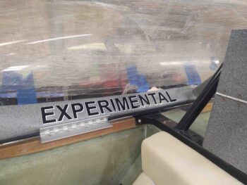
A closer shot . . .

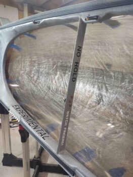
With the interior sides of my canopy near-vertical when closed, it makes the EXPERIMENTAL label near-horizontal when opened.  Luckily the plane is often in the grazing position with the canopy open which will make it make it much more visible.

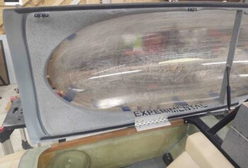
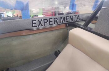
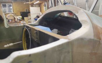
A shot somewhat from the back seat.

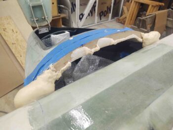
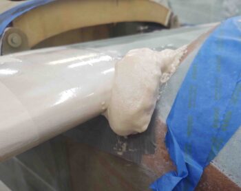
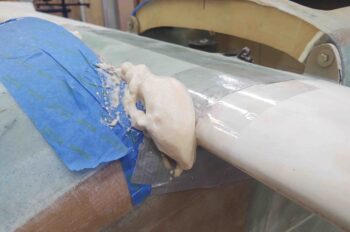
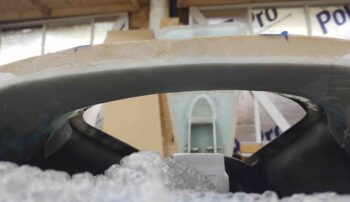
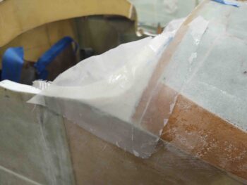
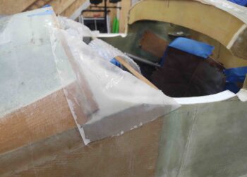
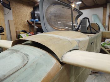
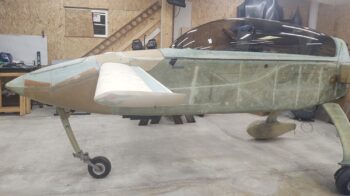
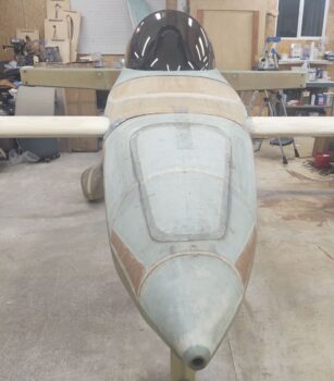
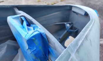
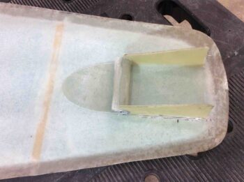
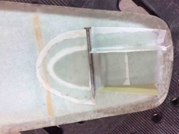
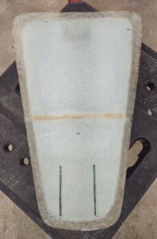
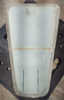
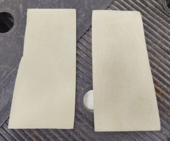
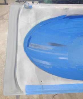
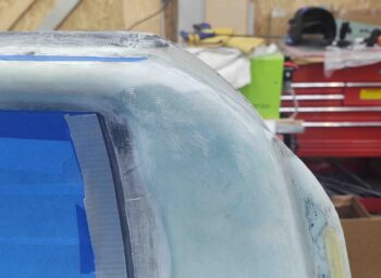
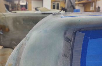
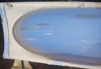
And a shot of the front canopy skirt.
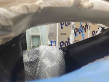
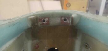
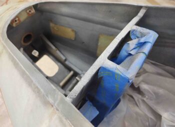
From inside:

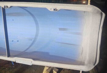
From outside (through canopy):

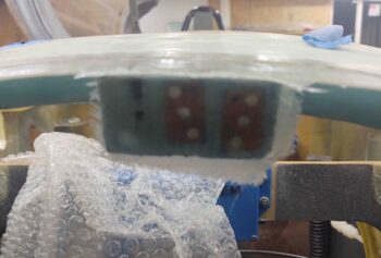
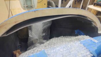
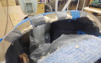
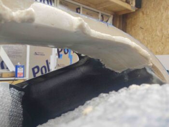
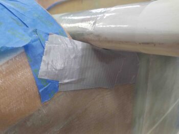
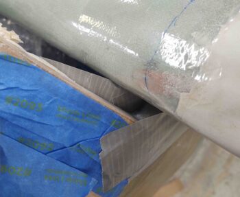
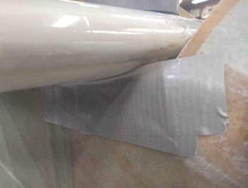
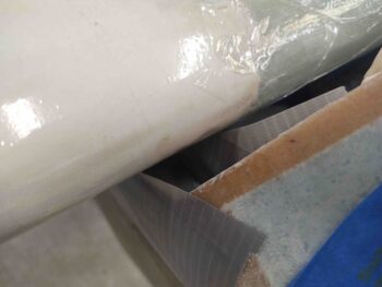
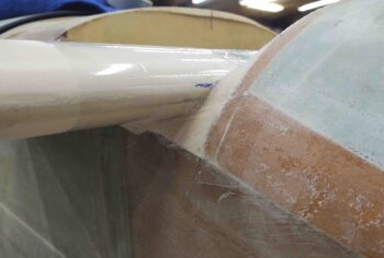
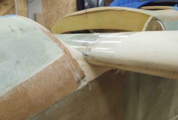
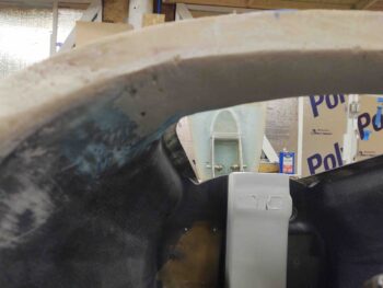
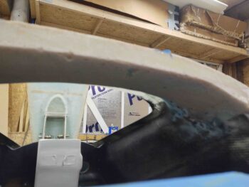
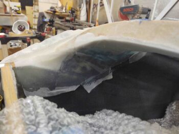
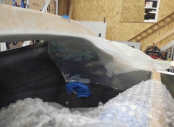
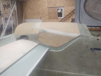
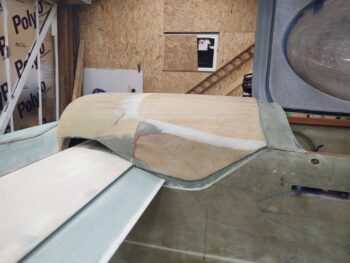
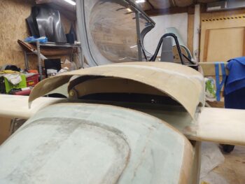
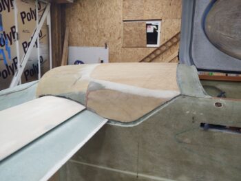
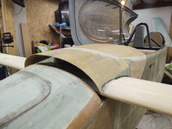
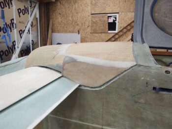
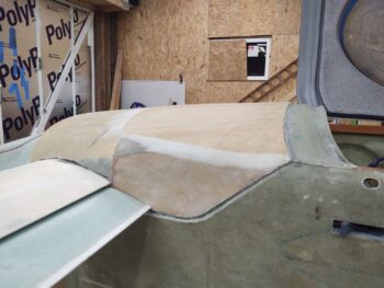
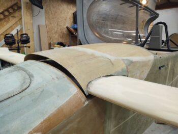
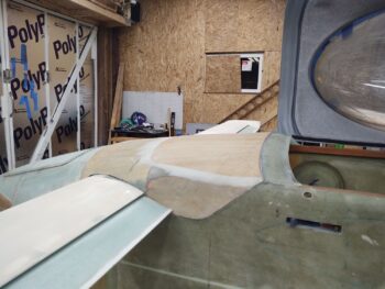
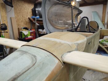
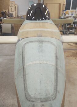
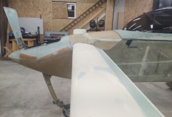
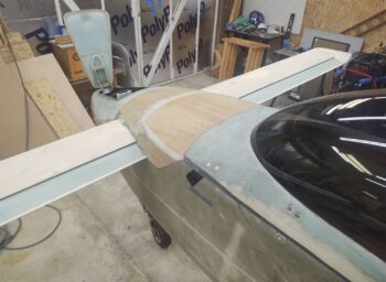
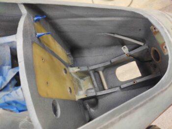
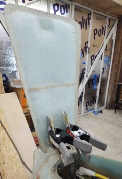
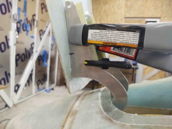
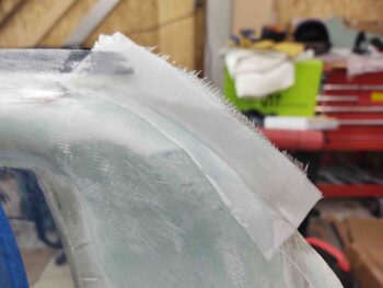
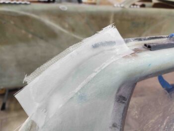
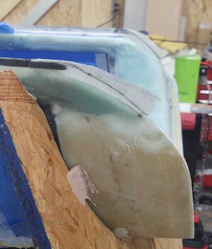
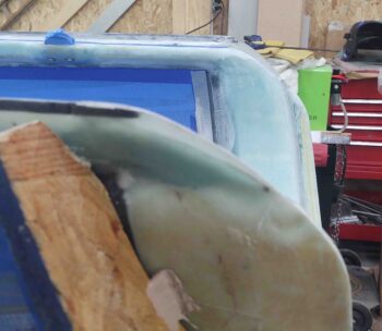
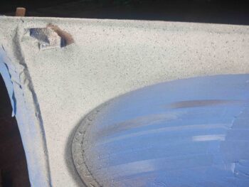
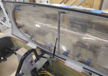
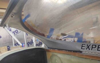
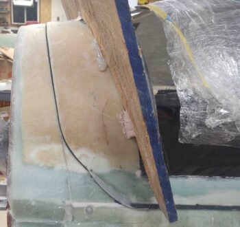
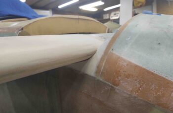
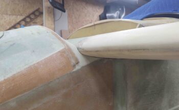
With new B-seals all around on the canopy, I grabbed some shots of the outside –each side–  to show the intersection alignment between the canopy edges and both the fuselage (side) and the aft nose/avionics cover (front).

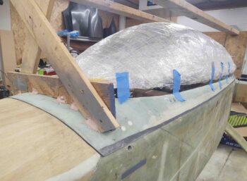
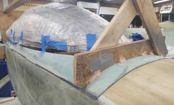
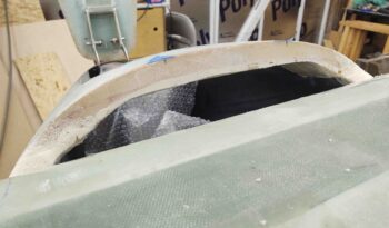
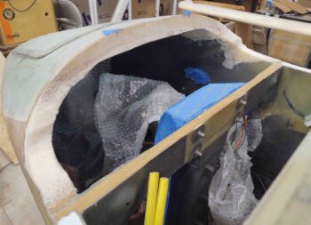
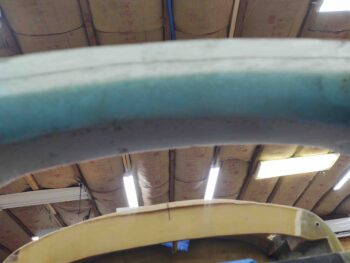
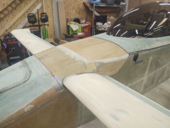
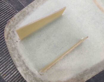
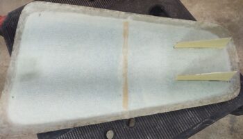
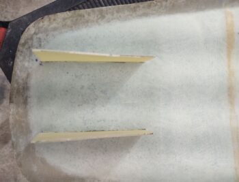
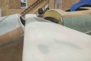
And a shot of the back canopy alignment with the Turtledeck.  Note the added glass flange in the lower aft “corner”… I’ll probably tweak that a bit more before final exterior paint.

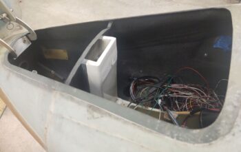
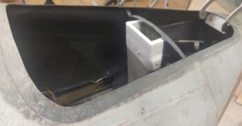
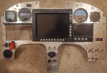
As I said earlier, while waiting for my small patches of gray stone paint to dry I figured I might as well get some work done on the panel.  Actually my fallback tasks were supposed to be on the nose, but I just felt like knocking some stuff out to get the panel as far along as possible today.

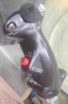
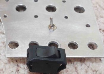
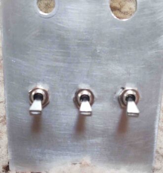
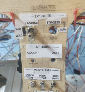
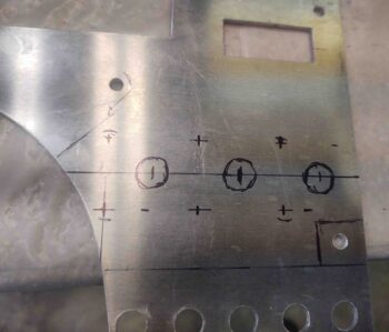
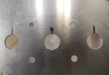
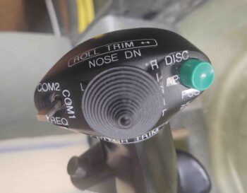
I re-drilled the lower left hole on the center strut for the small toggle switch, leaving only the 2 dimmer switch posts left on the strut to be checked and most likely re-drilled as well.  I then drilled out the holes in the upper right area for the 2 LEDs that make up the JBWilco gear & canopy panel indicators, and also the hole for the dimmer switch that controls the row of ON/OFF notification lights above the HXr EFIS.

Speaking of the row of ON/OFF indicator (“Korey”) lights, I finished dialing those in to allow mounting the entire row above the HXr EFIS.  I also trimmed the hole for the N-number N916WP Korey light in the upper LH corner, while finally getting the 2 outboard Korey annunciators for the GNS-480 completed as well.

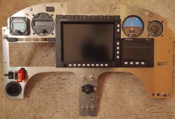
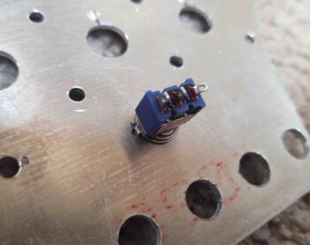
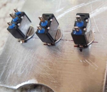
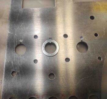
In the lower left corner I set the 2 rocker switches in place just to the left of the red switch-covered fuel pump switch (holes will need welded backfill on edges).  These rockers are for the engine intake RAM air valve and the oil cooler louver actuator to control/keep oil temp in the proper range.  I also cleaned up the hole for the eyeball air vent which will actually be mounted to the composite sub-panel and just peaking through this aluminum panel overlay. In the same way, the panel-mounted USB ports for each EFIS in the upper right corner (which I verified clearances are good) and the ELT remote control head (mid RHS) will all be mounted to the composite sub-panel vs this aluminum panel overlay, staying with the original any time I remove the aluminum panel.

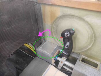
As I’ve noted a couple times since I’ve been back on the build, working a long extended project has is moments of scrambling to figure out either what past decisions were made, and/or a lot of times why!  Well, today I had to put on my Private Investigator’s hat and jump on the case of the missing panel ON/OFF indicator (Korey) lights’ Push-To-Test switch, which has traditionally –on my panel– been right next to the same lights’ dimmer switch.
Hmmm?  Where’d it go?

I went back to my couple-versions-old panel CAD drawing and there it was, next to the dimmer switch.  My latest panel version? Not there.

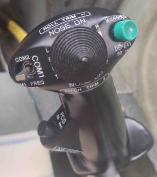
Yep, as I started thinking about it I remembered that with the new Warning Annunciator Sub-panel being plopped into the top center of the panel, I had to move some of the components in that immediate area to the side.  In short, the panel was getting a bit crowded there.  I pulled up the CAD drawing of the latest Warning Annunciation panel, that I was thinking I already had in my hot mitts, and there it was: a mounting hole on the right side for the panel ON/OFF indicator lights Push-to-Test button.

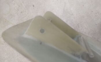
I finished tweaking the drawing since I needed to get the top front of the sub-panel up a bit higher to close the gap it had with the bottom of the glare shield.  To do this, I merely added more meat to the bottom flange of the sub-panel and angled the mounting base line (back wall) to tilt the panel up into position by providing a designed wedge under the bottom edge.

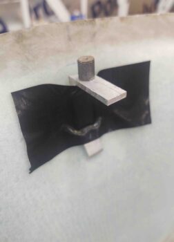
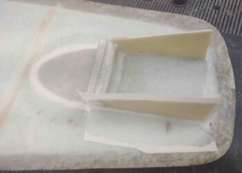
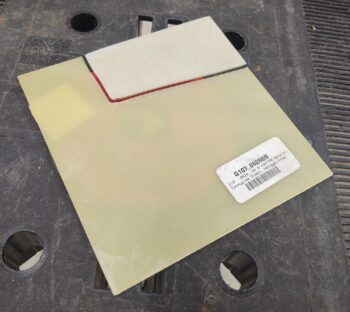
I then 3D printed the new Warning Annunciator Sub-panel, which took about 14 hours (I started this print job actually a couple hours before starting on the interior canopy paint clear coat).

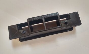
With the mounting back (technically forward side) now angled, but still printing the rest of the component vertically, it created a filled in wedge-shaped support raft immediately under all but the lowest/thickest lip of the back (against panel) wall (3D printed face up as in above pic).  Well, this didn’t provide the most secure attachment to the printer heat bed and some lifting on the lower attach corners occurred.  Nothing that can’t be dealt with or salvaged, but some judicious sanding will need to occur.

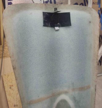
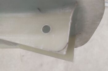
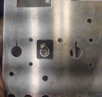
Regardless, here’s the missing Push-to-Test mounting hole!  Again, on the right side of the Warning Annunciator Sub-panel.

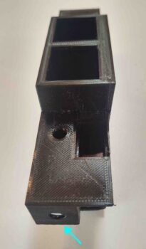
Unless the lifted-corner base is an insurmountable issue, I plan on this being the final version of the Warning Annunciator sub-panel.
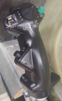
Chapter 18 – Canopy painted!

I started off today immediately laying up 2 plies of BID on each interior side of the canopy aft lower corner transitions between canopy and the Turtledeck.  Besides aesthetics, I’m hoping this will keep the wind noise down and the rain out.

I then peel plied the layups to ensure they would be as ready as possible later in order to get the interior of the canopy painted.

I then spent about an hour re-taping the canopy to protect it from the paint.

I then hit the canopy front lip with another 3 coats of dark gray paint + primer. There are still 2-3 slightly visible minor divots, but I’m calling this good and pressing on.

After all the canopy taping and re-painting the canopy front lip, enough time had passed that the canopy aft lower corner transition layups had cured.  I pulled the peel ply and then marked them (free hand) for cutting.

I cut the glass with a Fein saw and then cleaned up the edges with a hard sanding block.

Here are shots of the separate sides.

I then finished taping up the canopy specifically for the frame priming and painting.  I also added some lettering for my caution placards on the crossbar.  There’s actually black lettering on the black painted side of the crossbar.

I then took the canopy out in front of the shop and primed it first, then painted it with Rustoleum gray stone granite.

Here’s the front and aft side of the canopy after one coat.  It looked good so I didn’t spray another coat.

Once back inside, I removed the tape protecting the canopy front lip.  I really like the contrast between the dark gray and the granite paint.

I did end up hitting a number of spots with another coat once inside and I inspected it with the bright lights on the canopy frame.

I also removed the caution placard lettering on the crossbar before the paint cured too much to then make them difficult to extricate.

Also, although I don’t have a shot of it, I was going to put the EXPERIMENTAL placard on the canopy where the light gray primer block is just forward of the crossbar.  Once I pulled the tape I didn’t like how light it was.  At first I planned on repainting it with the dark gray, but then simply decided that the placard would probably adhere fine to the granite paint, so I just hit that spot with a couple coats of the granite paint.

Here’s a wide angle shot of the entire painted interior canopy.  It looks great and I’m really happy that I went with this paint, and even more that it’s done!

Since the gray stone paint requires 5+ hours to cure before clearing, I’ll shoot the matte clear coats tomorrow.