Chapter 18 – Canopy Wrap-Up

I started off today spending well over 2 hours finishing up the scratch removal/mitigation along the interior edge of the canopy where it meets the glass frame.  I also did one more step in the buffing out process along the interior perimeter of the canopy (approx. 6″ from frame).

I then gave the canopy lip a really good sanding with 220 grit paper, then wet sanded it with 320 grit… which really dialed it in.

I then assessed my Metal Glaze hardener and realized that the bottom part of the tube probably had usable hardener.  I snipped a corner off and tried it out.  Worked a treat and the glaze was rock solid in just a few minutes, so I used it on the canopy lip.  A bit later I realized I needed it in a few more spots so I whipped up another mini-batch and applied it to those spots.

About a half later I got to work on the Metal Glaze spots.  I used 100 grit sandpaper to knock down the majority of the applied Metal Glaze before switching to 220 grit paper.  After a bit (~45 min) of sanding with the 220 the lip is ready to go…. smooth as silk!

I need to re-tape up a good portion of the canopy for both painting the canopy frame, but the lip will get shot first.  Since it’s late I’ll do all that tomorrow.

I’ve been remiss in doing this next task, and should have gotten it done a day or two ago since it impacts the interior canopy frame painting.  I glassed 2 plies of BID to the aft lower edges of the canopy to allow me to create a nice transition from the added glass to each side frame, up around the aft “corner” of the canopy and the turtle deck.

Tomorrow the first task will be to do some Dremel work on the inside edge of the original canopy frame, add in a flox fillet and then glass 2 plies of BID from the inside onto each of these layups below.

I’m planning to be focused solely on the canopy starting in the morning.  With the scratch removal finished, I think I can finish the day tomorrow with the interior canopy frame at least painted… possibly even painted AND clear coated.


Chapter 18 – Scratch on, Scratch OFF

Within hours of discussing canopy scratch removal via email with my buddy Dave Berenholtz I watched a Long-EZ video on YouTube that lo and behold, along the edge of the canopy and frame junction were those rascally scratches that we were talking about. Now, if we hadn’t just been discussing them these scratches would have still been noticeable, but not what I would have been focusing on regarding the video content.

Moreover, after having just finished my diatribe in my project update of NOT seeking cosmetic perfection over build efficiency, here my first post out of the gate is about seeking cosmetics over an actual flying or safety-related requirement.  In fact, this post is ALL about cosmetics… ha!

The bottom line is this is one of those things where the scratches along the edge of the canopy are just too plain ugly for me to live with.  So, for me, I need to do what I can to best remove them.

And after some research and the very often helpful input from our RV-building brothers on the VAF site, I pulled the trigger on a Scratch Off kit from VANs.  I’ll point out that besides the overwhelmingly positive reviews and testaments I saw online, on the side of the box they highlight that this product is used by NASA…. not too shabby.

With that knowledge in hand, I invoked Tony Stark’s line in Iron Man, “sometimes you have to run before you can crawl” (or something like that!).  I chose the most inconspicuous spot for viewing for either me (pilot) or GIB to test a scratch to remove.  Clearly this would show if the canopy were open at a fly-in if the test were a fail, but I figured I needed to press forward.

In the instructions for the Scratch Off kit it notes that they do not necessarily recommend the use of wet sanding, but that their kit picks up where 600 grit sandpaper leaves off.  In other words, if you have deeper scratches then some sanding will be required to remove them.  They recommend 600 grit, but I only had 500 or 800 grit (and higher) on hand, so 800 it was.

I first tried just using the Scratch Off kit for two distinct scratches on the upper aft edge of the canopy.  Grant it, I was only using it by hand and the kit is made to be used with a powered hand drill.  After using the most abrasive solution and pad included in the kit with no removal of the scratches, I resorted to using 800 grit wet sanding of the scratches (blue arrows).

If this isn’t a test of faith, then I don’t know what is!

Again, by hand, I proceeded to use the most abrasive solution and pad included in the kit and was able to nearly completely buff out the scratches I had made in removing the deeper scratches.  Satisfied, with this test, I pressed onward . . .

… to this area.  Probably the worst area on my canopy for scratches.  It’s located on the left side just forward of the aft corner.  Moreover, I decided to simply use an entire wet sanding protocol starting with 800 grit, then moving upward in finer papers to 1000, 1200, 1500 and then 2000 before then using the Scratch Off kit.

Yep, this looks pretty ugly after all the wet sanding was complete (gulp!).

But even just after the first round (I still have the finer solution and pad to use) the wet sanding marks were removed.  The myriad of finer scratches are gone, while the deepest scratches are still visible, but greatly minimized in depth and severity.

I should note here that I’m doing this scratch removal on the interior canopy now since I’m prepping the interior canopy frame for painting.  I really don’t want to paint the canopy frame (either interior or exterior) to then subject the painted edge to a spinning foam applicator AFTERWARDS and risk damaging the paint.  Thus, in my mind it’s either now or never for removing scratches along the edge of the canopy.

With that said, some of the scratches you may see in these pictures are actually on the exterior canopy surface.  I’ll do what I can to remove/mitigate those scratches on the exterior canopy surface later, prior to painting the exterior canopy frame.

Again, my buddy Greg and his wife Marie were in the area and stopped by for a visit.  I was just finishing up buffing out the edge scratches on the forward half of the left hand side of the canopy when they showed up.  In all, I was able to get over 2 hours in on the canopy, finishing the majority of the back edge and the left side almost up to the front center point.

I will highlight that as per usual in these types of endeavors, that after working the aft left side my confidence grew immensely in using the wet sanding protocol followed by cleaning up the sanding scratches/marks with the Scratch Off kit.  I highlight this because it’s a bit difficult to figure out what side the scratches are on for every scratch.  The deeper scratches you can feel with your fingernail, but the lighter ones, although visible, aren’t quite as easy to ascertain what side they’re on.

So on the forward (pilot) edge of the left side I simply wet-sanded nearly the entire edge to clear away as many scratches as possible before getting the first of the four Scratch Off kit steps completed before my friends arrived.

My goal tomorrow will be to knock out the scratch removal on the interior edge for the remainder (right side) of the canopy.  I will then prep the interior canopy frame and paint it.


Chapter 13/18 – Hatch & Canopy

Today I started out by getting some epoxy/layup work done out of the gate so it would cure as I did a bit of machining.

First up is what will be a glass tab, or catch if you will, that will simply be a semicircular “C” shape on the underside of the nose hatch door with the opening facing aft.  It will snap into place on a simple 1/2″ diameter 6061 crossbar bolted in between the tips of each hinge. Add an aircraft locking pin between an added underside flange on the nose door and each hinge to make it so that the nose hatch door will be removable…  to make the remainder of the build easier and for when a lot of work needs to be done in the nose hatch area and the door is simply getting in the way.

I used a different 1/2″ tube than the one I was machining on the lathe as the mold, and simply laid up about a 4×4 inch ply of BID, a middle ply of UNI, and another ply of BID with peel ply on both sides.  I then wrapped one end around the 1/2″ tube and duct taped it into place.  I then had to set a couple of objects on each side to keep it from unrolling.

The cured layup is at the end of this post.

I then used the small bit of epoxy left over from the layup above to whip up some micro to fill in some holes, divots, scratches, etc. on the front lip.  I would normally use my Metal Glaze filling compound for these small filing jobs, works much better, but I found that my hardener for that is toast… will have to order some more.  So I tried some micro for the minor fills I’m doing here.

I then left both of my epoxy-tasks to cure…

And rounded up a spare 1/2″ 6061 rod.  I was thinking about re-using my 1/2″ elevator control tube with the aluminum Heim end-caps at the end for my bolted-in hinge crossbar, but with the design of my hinge door tab it will wrap around the bar and thus rivets are out since they would require the tab to be much narrower to avoid the rivets on each end.  If I simply drilled a hole all the way through this less-than-3″-wide solid bar it would be very reasonably close in weight.

I started by facing (cleaning up) one end with a very slight bevel on the edge to “break the edge” and avoid any more cut fingers (I have a healing nice big gash on my thumb from a machined edge that I grabbed hold of . . .).  I center drilled the end to then use a #21 drill bit to drill over 1-1/2″ down the center of the rod.

From there I simply threaded the drilled hole out with a 10-28 tap.  Voila! Side 1 complete.

The hinge crossbar needs to be 2.9″ long, so I cut the rod at 2.95″ on my horizontal bandsaw.

I chucked it up with the unfinished end facing out (of course) and did the same thing as before: facing (although with the lighting [lesson learned] I noted at the very end that I hadn’t faced it all the way and had to redo it), bevel, center drill, #21 drilling (end-to-end), and 10-28 thread tapping.

Here’s a closer look at one of the finished ends.

I then grabbed a couple of short 10-28 bolts off the workbench and installed the freshly made crossbar.  Fits a treat!

Another shot, showing clearance with the tool box.  It just barely touches the tool box latch, but then again it won’t sit this low when mounted to the the underside of the nose hatch door. It will be a couple of inches higher (towards the camera) and completely clear of the tool box latch.

In the meantime I had taken the canopy outside in front of the shop and hit the front lip with a few good coats of darker gray paint + primer.  I will sand this down and do some final tweaks (yep, really missing my Metal Glaze!) before a couple coats of final paint.  I’m not looking for perfect here, but there are a few glaring areas I want gone.  Compared to how this thing looked just a few short weeks ago, it’s a vast improvement.

I then spent a few hours doing the final trimming and cleaning up of the glass edge around the interior perimeter of the canopy.  The amount of small pieces of yellow painters tape was surprising… I had missed a fair bit on my initial cleanup.  But being this is the last cleanup session before final interior paint, I was much more thorough this time around.

I then removed the 1/2″ tube and the peel ply from my nose hinge/nose door mounting tab.  The diameter is a hair larger than I want (from the tape on the tube) so when I open it up into a “C” shape I’ll need to add a few plies of glass to the inside diameter.

I slid yet another spare 1/2″ tube in place so you can see somewhat how it will look when installed.  The first pic as if looking through the top nose hatch door.  The second pic from inside the nose hatch door.

If you’re wondering about the long flat part of my strange contraption here, it is simply to provide an aft side mounting flange to this tab, and a bit of rigidity.  Since the underside of the door is curved, I’ll have to fill-in under the circular tab a little bit with micro/flox when it gets installed. I’ll also trim the flat part into more of a rounded “V” or “U” shape to fit in the underside door curve better.  After a decent-sized fillet on the front intersecting area with the door (right side in pic), more BID will be added going forward.  Each end (top  & bottom in pic) will also intersect with the respective vertical flanges that will be installed forward of this tab to interface/mount to each of the hinges.

Tomorrow will be a short build day since I have a buddy of mine, that I haven’t seen in over a year, coming to town.  So dinner, libations and war stories will be the planned events for early evening on.  I will try to get the canopy edges at least cleaned with the ScratchOff kit I got from VANs Aircraft.  It that goes smoothly and quickly, then I may actually get the interior canopy frame painted.

Chapter 13/18 – 6061 nose hinges cut

I had a number of other things going on today other than the build.  A few errands and had to help a friend out with some stuff.  I also hung out with my little buddy a bit, so I didn’t get an entire day in on the build.

I did spend a good half hour plus sanding the front lip of the canopy to dial it in a bit more. As I mentioned in my previous blog post, since the front lip interfaces with the nose-side glare shield I won’t be using speckled granite paint on the lip (or the glare shield).

I got another few coats of primer on the lip, and for comparison’s sake jumped ahead a few hours with the pics side by side.  Two points of note are that A) I will be –again– going with a much darker gray for the final color on the lip, and B) although not quite visible on camera, I still need to clean up a half dozen spots, divots, etc. and re-sand before any further coats.

I did a bit more research on my CAD options since, as I explained. my plasma table was currently out of commission with the changes AutoDesk made to the rapid movements in post processing CAD files for machining, plasma cutting, etc.  I thought long and hard about this both last night and up until this afternoon, and figured I couldn’t afford to do the proverbial switching horses mid-stream, so I relented to what is in my opinion akin to extortion and purchased a 1-year license for Fusion 360 CAD.  There’s simply too much I need to get done as quick as possible between plasma cutting, milling and lathing, that I simply cannot be non-operational with any of the machines I have.

Within minutes of pulling the trigger on my new and improved Fusion 360 CAD (Wrong! I essentially bought back rapids) I was able to use my plasma cutting table again.  With that, I cut my latest –and very hopefully final– set of hinges out of the same 0.090″ 6061 aluminum that the instrument panel was cut from. Thus, I’m “proud” to present to you my very costly nose hatch hinges! (yes, I’m being particularly facetious . . . ).

I then took about 20 minutes to clean up the welds a bit on the nose hatch hinge bracket and attached the 6061 hinges to the bracket.

I’m cautiously optimistic and very hopeful that these guys are the ones…. they fit great and the geometry looks very good so far (again, thanks to Mike Toomey for his advice on these crazy nose hinges).

Here’s a shot of the installed nose hatch hinge bracket with the nose hatch hinges installed.

Tomorrow I plan to focus primarily on the canopy: removing scratches from the edges, doing a layup or two in a couple spots, and painting the frame (if time).  So whether tomorrow, or soon, I will be working to attach the nose hatch door to these hinges!

Chapter 13/18/22 – Time Capsule…

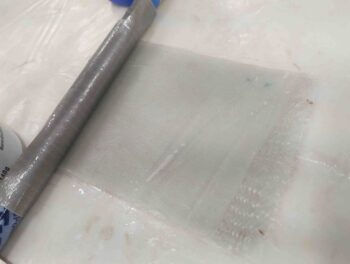
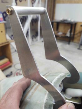
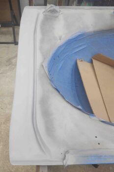
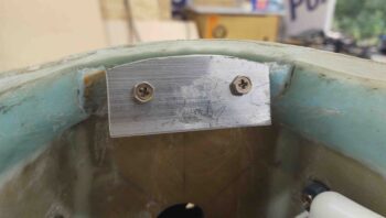
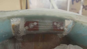
I started off today by adding another ply of BID to the face and underside of the block of H250 foam which makes up the sub-structure and holds the securing nutplate assemblies for the nose hatch hinge bracket.  Unlike the previous 2 plies of BID that I laid up to secure the nutplate assemblies, this ply overlaps onto the underside of the hatch lip and on the underside of the H250 foam protrusion (which already had glass on the bottom side).

Since this hinge bracket sub-structure will be hidden primarily by the hinge bracket, I only peel plied the strip just under the hatch lip.

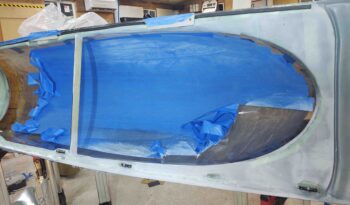
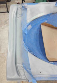
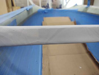
I then got to work on the canopy.  I reshot a couple of coats of white and black on the aft side of the crossbar (not shown) after I plugged a myriad of pinholes with micro.  I then hit the front half of the interior canopy frame with gray primer, my real target being the front lip from the seal groove forward.  Since this surface contour mirrors the glare shield on the aft nose/avionics cover, I don’t want to use the nice flaw-hiding granite rock paint since the build will be too high and most likely end up transferring gray granite paint to my black glare shield.  Or worse, act as a glue on a hot day and really mess things up!

After the front lip cured for a couple of hours, I went back over it with some raw epoxy in a few areas and some micro to help fill in some divots and hide some imprinting glass weave that was showing through.  Tomorrow I’ll sand and hit it with another coat… but most likely pick up some darker gray primer or paint, since this is too light in color for what I want.

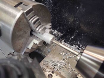
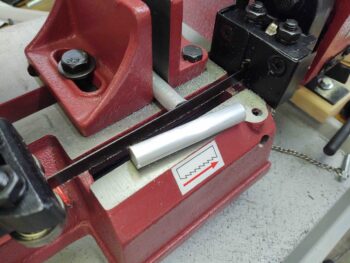
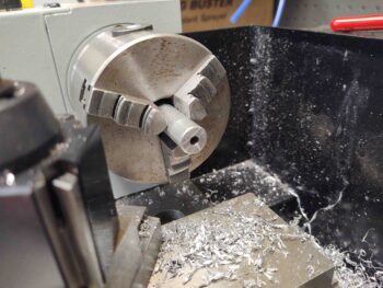
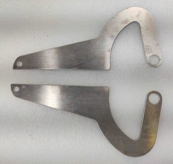
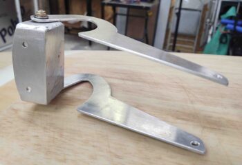
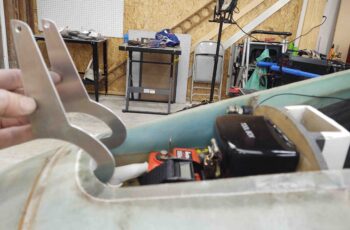
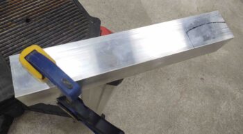
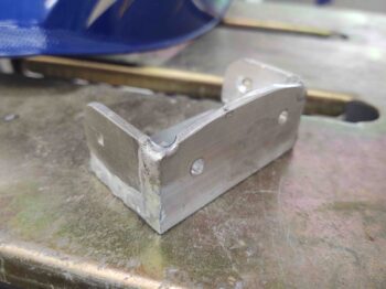
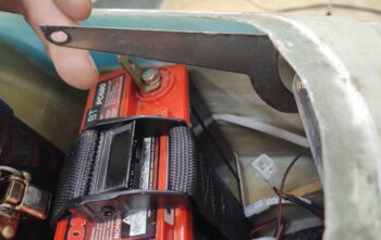
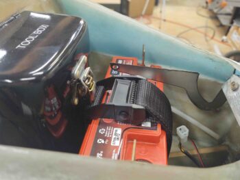
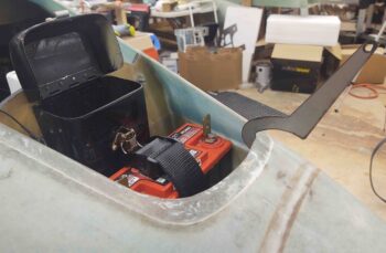
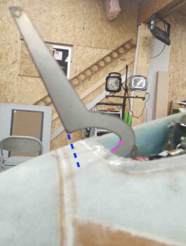
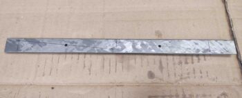
As the first rounds of canopy paint were curing I got to work on a long overdue task, and one that really needs to be completed pre-strake build.  This was the impetus for my welding up the “ugly wrench” last week to remove the 1/2″ oil heat lines coming in from the Hell Hole along the left side of the GIB thigh support/fuel sump structure and terminating each into a 1/2″-to-3/8″ reducer.

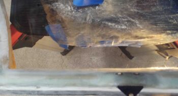
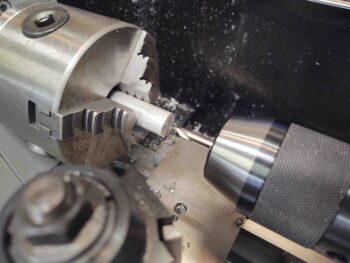
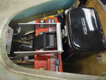
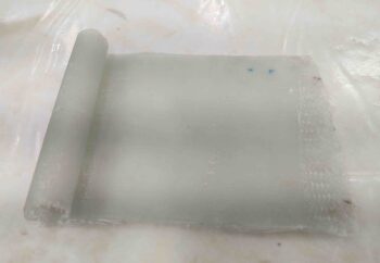
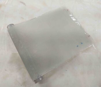
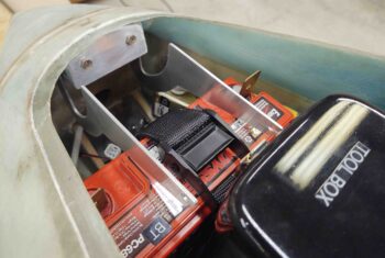
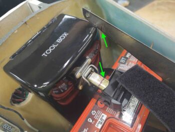
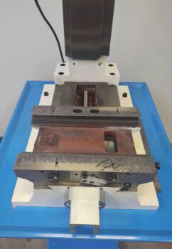
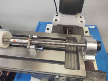
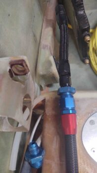
Here, from bottom (aft) up (fwd) is the black 1/2″ oil line with its red & blue fitting, connected to the blue reducer (also shown lower left), with the black fitting of the 3/8″ oil hose connected to the forward side.  Note the black heat exchanger in the upper right corner where the 3/8″ lines connect to.

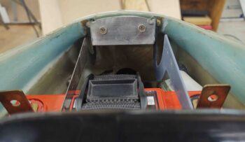
As typical, a lack of planning and a true understanding of operational impact and future maintainability bit me in the butt.  At the point I created the hex-shaped pass-thrus in the GIB thigh support/fuel sump side bulkhead, I didn’t consider the left tank fuel and vent line tubing covering up these oil hoses and thus denying access to get a wrench in there to torque them to final specs… which would still have been a fairly difficult task in itself with nothing in the way.

To compound my self-inflicted difficulties, I only made the bulkhead hex pass-thrus big enough to accept the reducers’ hex nut coming in from the front of the bulkhead.  The back of these holes had about a 0.2″ lip to keep the reducers from freely sliding through the bulkhead.  My aim in securing them became a huge nightmare when I had to extract the 1/2″ oil line fittings in order to tighten them to spec (which they haven’t been this entire time since installed . . . years).

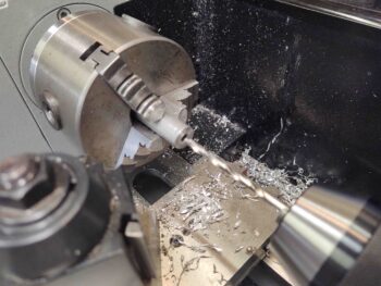
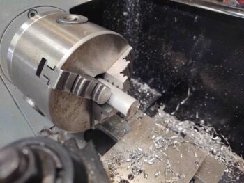
So I remedied that today with nearly an hour of careful (as possible) Fein saw work and manual sanding.  But I eventually got the bulkhead hex passthrough lips removed so that I can preassemble the entire oil line hose assembly (as per pic above):
                                         1/2″ hose ⇔ reducer ⇔ 3/8″ hose
all tightened to specs and then slide it through the bulkhead hex holes.  I will then, as before, just use silicone to hold the reducers in place in the hex-shaped bulkhead holes.

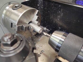
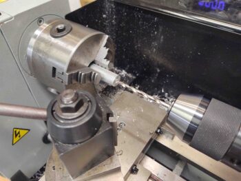
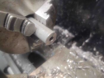
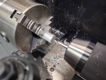
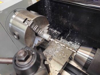
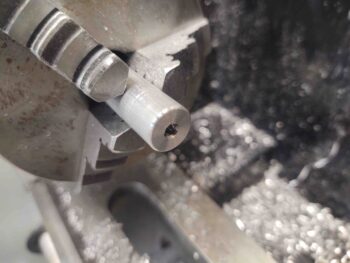
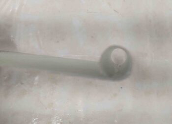
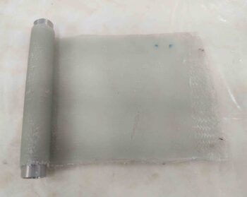
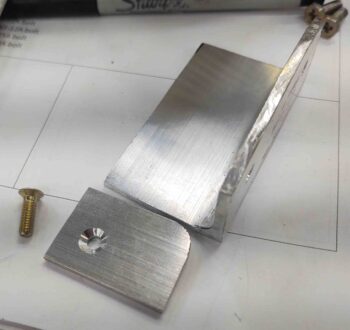
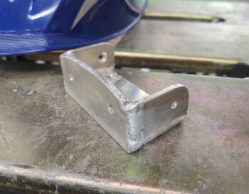
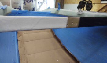
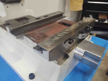
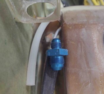
Here’s a closeup of one of the reducers.

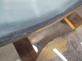
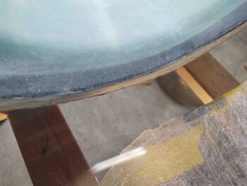
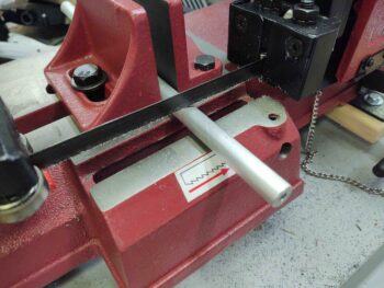
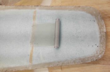
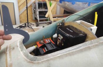
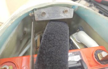
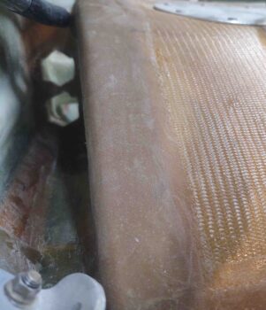
I also spent a little bit of time to knock down the thin edge that makes up the 1/2″ oil line transit hole going through the lower left GIB seat.  Note the black line I marked as my target cut line.

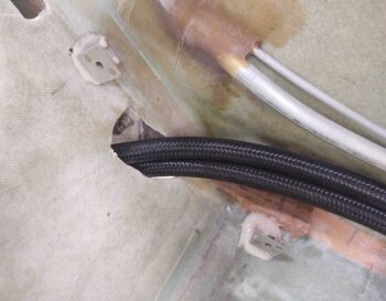
Here I’ve cut away the seat glass edge that had the potential to gnaw into the heat oil hose.  I will also add a sleeves to protect the hoses further, but this was a good start to remove any potential “knife / saw” edges.

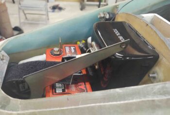
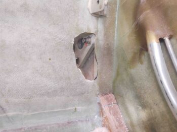
A shot of the oil lines back in place, transiting through the GIB seatback.

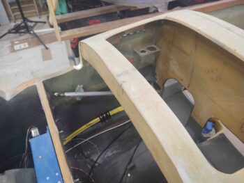
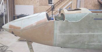
It was at this point I finally cracked open the time capsule that is the aft nose/avionics cover.  It took me a good half hour of gentle prying, coaxing, coercing and pleading for this thing to come off without any major damage!

Here’s the nose side of these shenanigans.  A site I haven’t seen in well over 2 years.

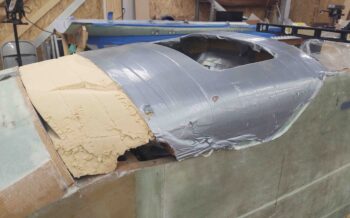
Another shot from the front.

I then started the seemingly unending task of removing tape and cleaning up the structure underneath the tape.  This took a couple of hours.

The protective plastic I had in place all during the glassing of the aft nose/avionics hatch sub-structure was still in place.

I removed the plastic and tape, and a few plies of old peel ply in the corners.  I then gave the avionics bay a fairly thorough cleaning and vacuumed it out.

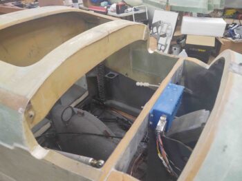
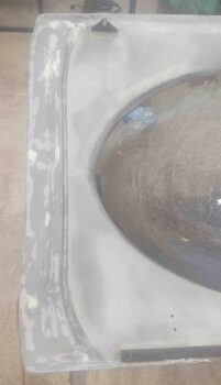
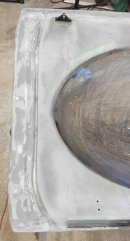
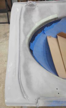
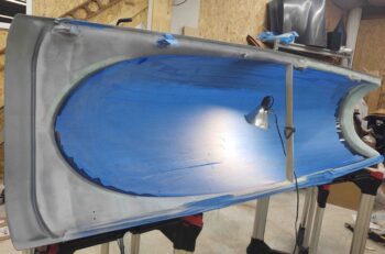
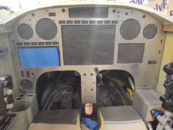
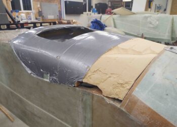
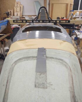
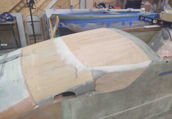
I grabbed this shot of the glare shield substructure from the top side.

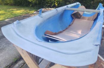
And from below… not something normally visible when the nose cover & glare shield are in place.

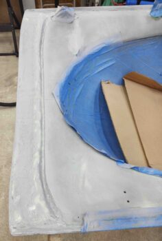
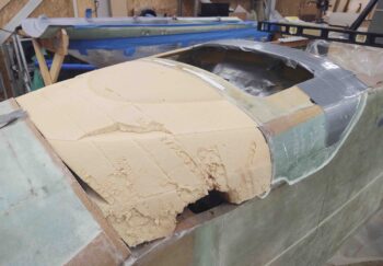
I also grabbed this side view shot showing the nose pocket where the canard will get mounted.  I’ll be adding pour foam and glass in the forward lower corners of the pocket around and matching the lower forward contour of the canard.

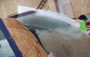
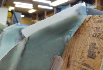
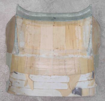
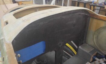
I then spent over 30 min cleaning up the underside of the aft nose/avionics cover.  I cleaned off a bunch of dead glass and pulled a fair amount of peel ply.  I’ll be giving it a very thorough sanding on the inside.  Also, since I had to add an extra layer of wood on the top aft area of the cover for a better contour, I’ll remove a good portion of the lower (inside) layer of wood and then glass it for some weight reduction.

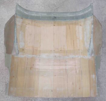
With the cover curing for over 2 years, it held its shape beautifully when I set it back in place.  I’m pretty excited to see how this cover will look and function once the install is finished.

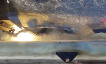
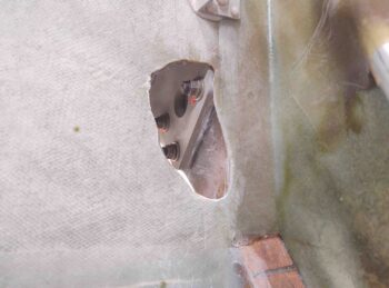
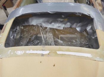
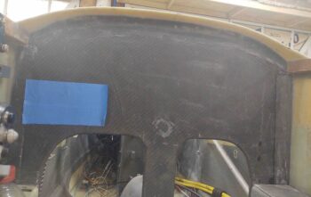
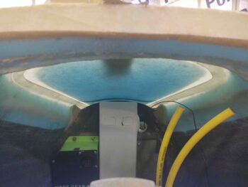
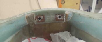
With the aft nose/avionics cover off I took this interesting shot of the forward nose hatch from inside the nose…. I think it looks pretty cool! (can you see Napster peaking out??)

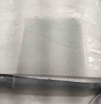
Speaking of nose hatch, here’s the cleaned up 1-ply BID layup from before. It was still just a very tad bit soft, so I’ll sand the edges tomorrow when it’s cured a good 12 hours more.

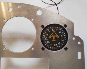
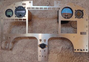
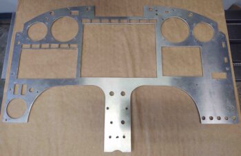
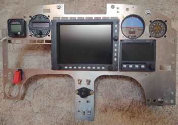
Also, I actually did a fair amount of work on the instrument panel today, a bit here and a bit there… but about an hour-and-a-half total.  I had to increase the height and width of the GRT HXr EFIS opening a bit in both directions, and also work to square it up some too.

This plasma cut was an odd one since the HXr opening was one of the first cuts out of the gate, and it was a bit off as well.  Not horrible, but the row of Korey indicator lights above the HXr is definitely off in relation to the EFIS, and will need a good 2-3 hours to dial in. Moreover, with these indicator lights I’ll now be relying more on the composite sub-panel structure to secure them vs this overlying metal panel.

The push continues . . .

Chapter 13/18/22 – Hinge bracket #2

A major pitfall of a long airplane build is simply keeping track of all the massive amounts of data swirling around for each step of the build.  It’s easy to say that we’ll verify each and every piece of information, but the truth of the matter is stuff falls through the cracks…. or I should quantify all this with the statement that it definitely does so for me at times.

Thus, my assumptions that past Wade had done right by present Wade may have been a bit optimistic in the case of the pair of rocker switches on my panel.  I had a rocker switch already targeted for my RAM air open/close switch, but a wiring configuration change quite a while ago ended up making that one obsolete.

Moreover, its twin was to be used to control the oil cooler louver actuator to allow for oil temp to be controlled remotely (and accurately via the EFIS display) from the pilot’s seat. Well that design never came to full fruition, so rocker switch number 2 was also dead in the water before it ever made it to the panel.

Well, it was then probably serendipitous that if any part of the panel plasma cutout was to be kluged, it would be these rocker switch cutouts… because after a good hour+ of research I was able to find a pair of rocker switches that met the wiring & operational use requirements, while only being just a scant tad off from the original panel hole size for mounting.  So I pulled the trigger on those . . .

Out in the shop I grabbed a piece of angle 6061 aluminum and got to work on the new nose hatch hinge bracket… clamping it down for cutting.

Here we have the new nose hatch hinge bracket after cutting it out of the angled aluminum extrusion.  As you can see I transferred the bolt mounting hole positions from the old bracket to the new one and bolted the new one into place.

I then got to work on the sides.  Here we have the left side wall of the nose hatch hinge bracket shaped, drilled and ready to be welded into place.

Welding 1/8″ sides to the same 1/8″ thick bracket front wall and bottom went much smoother this time around.  These pics are of the welded bracket without any clean-up of the welds.

Again: much, much better than the initial bracket (I will do some clean-up on the welds, but nice not to have to test fit it!).

I then bolted the freshly welded nose hatch hinge bracket into place, with a couple of test hinges attached.

I thought I’d post a better shot of the trimmed tool box latch handle… I even turned the battery securing belt around to see if it made any difference in clearance, which it didn’t.

With the hinges mounted much further forward (as per Mike Toomey’s recommendation), you can see that the last test hinge that I cut doesn’t even clear the hatch’s front lip.

One of the original 3D-printed test hinges now looks much better in its hinge geometry, although the alignment with the door bottom surface is still off.

I collected notes on some tweaks I needed to make for the final (hopefully) hinge configurations and updated my Fusion 360 CAD drawing.  Fusion 360 (Autodesk) has changed its free CAD software version so when I went to cut out the final hinges on the plasma cutting table I got an error.  When I looked up the error on the Langmuir Systems plasma cutting forum I saw that a number of Fusion 360 users are getting the same error… so I, like thousands of hobbyists around the world, have some decisions to make [btw, Marco and I discussed this issue a fair bit last week… I didn’t realize it would effect my plasma cutting table ops].

Of course I have a ton of other tasks to work on, so I taped up the canopy and painted the cross support bar white on the right side and black on the left, just on the aft side facing the GIB/passenger.  These colors will be used as background colors for “NO HOLD” and “WATCH FINGERS” warnings on the cross bar.  The fingers warning on the side where the canopy strut scissors up and down.

As the paint was drying I realized I had a number of pin holes on the surface.  And since I was mixing up some micro to apply to the canopy front lip . . .

I went ahead and slathered some on both the white and black painted surfaces of the canopy crossbar.  I’ll hit both colors with another coat or two tomorrow.

I then called it a night.


Chapter 13/18/22 – Panel Bits

Today I started off with some fairly in-depth research on how to install the nose hatch door “J” hinges in a manner and configuration where they will simply work.

So I discussed hinge configurations back and forth some with Terry Schubert.  In addition, when I found out Terry Lamp and Mike Toomey were down in Chesapeake visiting Marco and Chris Cleaver to help them with their respective condition inspections, I called and spoke with both Terry and Mike.

Terry deferred to Mike, and Mike had some good advice.  I think if I have any hope in actually getting these hinges to work, it will be on his word that I should mount the hinge pivot points as high and as forward as feasibly possible.

Thus, towards the end of the evening I Dremeled out as far forward as I could in the channels I’ve created on each side of the nose hatch hinge bracket.

I’ll see if I can make the hinges work, which obviously I’d really like and really prefer, but I’m not going to continue to spend countless hours on them.  If I get no joy on the next round of hinge efforts, I’ll have to really consider going in a different direction.

I did spend a couple of hours “playing” around with the canopy and looking around to locate some electrical components.  I started off by installing the vertical compass card which fit fine, as did the screws in the holes.

Apparently the cutting action of the plasma creates a beveled kerf on the bottom half of the round cutouts, since every hole required some cleanup almost completely just on the bottom half.  After about 10 minutes of filing, the holes were good to go to mount the top instruments into (from left: MGL clock/timer, Trio autopilot, TruTrak ADI, and vertical card compass).

Moreover, of the 16 mounting holes that were plasma cut, only one requires drilling to provide about 0.020″ extra clearance for the screw.

The holes in the center strut were NOT as impressive as up top.  For some reason these lower holes were all cut about 0.050″ to 0.100″ to the left of where they should be.  I drilled the top (light switches), second (RAM mount) and fourth (component ON/OFF switches) row holes, essentially making them oval vs round.  I’ll assess as I go along whether I need to fill in the edge of each hole by TIG welding in some filler aluminum.

I then spent a good couple hours on the canopy, after removing it from the fuselage. Sorry, no pics.

I filled in with micro the last few areas on the interior side that needed it, and then got to work on the left-side canopy frame to sand/remove as much of the flocro I had added to the underside to make the surface straight and fill in any depressions.  The bottom line is that it was just too much flocro and wouldn’t allow for me to have the canopy seal in place with a good interface with the aft turtledeck or the front-side aft nose/avionics cover.  So I vigorously removed as much flocro as possible while still maintaining a straight surface.

Tomorrow I’ll continue working nose and canopy tasks, while also doing a bit more on the panel to prep/populate another 5-6 more vacant holes.


Chapter 13/22 – Instrument Panel Cut

As in, the REAL 6061 aluminum instrument panel!

I spent quite a bit of time in Fusion 360 CAD today.  I got a bit of a late start, and it was quite the dark rainy day.  So I had a cup of coffee (or two) and knocked out the CAD updates for the both the instrument panel and the a new, shorter nose hatch hinge.

I then plasma cut the instrument panel out of a sheet of 0.090″ thick 6061 aluminum, as I documented in this video:


Here’s how it looked after I cleaned it up a bit.  It definitely wasn’t the best plasma cutting session I’ve had, but there were no major tragedies or damage, so this dog will hunt!

I then test-fit the freshly cut panel in the cockpit, over the stock composite panel (which will serve as a backing/reinforcement panel structure).  Not surprisingly, as one would hope, it fits the best by far of all the panel variants.

I also plasma cut a new nose hatch door hinge.  The size fit is good, but I’m still off on general configuration, as I have been on all these hinges.  There is clearly a configuration trick that I am missing, so I’m going to have to do some remedial research and possibly call around for some help from folks who have done this.

Again, the primary issue is getting the hinges configured so that when the hatch door is open, the door front lip IS NOT resting on the top forward surface of the nose.

And although it’s hard to tell, I also trimmed the length of the tool box locking latch lever to allow it to clear the (now) secured battery strap.

Here we have both the new (shorter) nose hatch hinge in the open position and the tool box –with its now shorter trimmed latch handle– also open, the latter now being able to be manipulated with the battery strap & buckle secured in place.

Tomorrow I plan on continuing to press forward with the nose build, and also most likely finish up some on the canopy interior as well.


Chapter 13 – Clearance Issues

I started out today with multiple successive cuts just under the front nose hatch lip on each side of the hinge bracket to allow for the hinge and retaining nut to slide into place. Remember, I cracked the right side half off so I can’t test fit a hinge there, but one hinge will do what I need here.  Yes, still need to make a new bracket . . .

I put the battery back in the nose, because I was focusing mainly on that clearance with the hinge.  I quickly realized I needed to go grab my tool box and put it back in place to check that clearance as well with my longer hinge.

To then realize further that I had some issues to resolve.  My new longer hinge is over an inch too long for clearing the tool box.

Moreover, I apparently never vetted the tool box’s clasp operation with the rather robust battery securing strap I have around the center of the battery.  The clasp arm snags in opening and closing on the battery strap clasp… by about 1/8″.

Solution? You can see the line I made on the tool box clasp to simply trim it down.  There’s not a ton of force required on the clasp to open or close it, so I don’t foresee any issues with cutting it a bit shorter.

After playing around with the door and setting it where it would be in place aligned with the hinge, I quickly realized I have a hinge alignment issue.  I tested it out a little with the older “wrong-angled” hinge and I don’t think it’s due to the new angled hinges, but at this point simply because the “U” part of the hinge is too big.

The gap between the double magenta dashes (bottom trough of “U”) and the front edge of the hatch needs to be reduce to almost nil.  Moreover, the height between the front connecting edge of the hinge (top of “U”) at the blue dashed line needs to be minimized quite a bit as well, since with this current configuration the front tip of the hatch door would rest on the top of the nose (not good) versus the front lip of the nose hatch stopping the hinge travel when the door is opened fully, as in this pic.

In addition, I think moving the hinge pivot point as far forward as possible should help mitigate my nose hatch door hinge opening geometry issue.

I think I can say authoritatively I now understand why builders go with either the external CAMLOC/screw or the wire-through-embedded tube methods to secure the hatch door to the nose, because this hinge-solution is turning into quite the cluster.

So knowing I had to go back to a few different drawing boards, I called “Uncle!” for the time being on the nose hatch and went to work on the milling machine reassembly.

I started with the Y-axis gib on the saddle.  I marked and drilled the 1/8″ pilot through hole to allow oil to come in from the new fitting.

Then, based off the through-hole I marked up the oil distribution channels. These will be used to spread oil fairly evenly on the mating way surfaces.

I then used the Dremel tool to cut about a 1mm deep trough along the lines.

I then pulled the X-axis gib, which is also located on the saddle, and did nearly exactly the same thing as above.  Except the X-axis gib has 2 oil through-holes.

With that, the mods to all my gibs are all complete with all having much better oil distribution pathways now for far increased lubrication capabilities via the One-shot oiler system.

The current limiting factor is that my ball oil conversions via drilling and tapping aren’t going according to plan.  Just not enough meat left over, so it’s proving hard to really secure the threaded push-tubing fittings into the converted ball oilers.  I’ll need to make up some press-fit threaded adapters on the lathe once I complete its CNC conversion as well.

Nonetheless, I was able to get my saddle re-installed onto the mill base.
(BTW, the Y-axis gib is located where the round flat screw is located on the lower right, near the angled way… and you can see the X-axis gib screw sticking out to the right at the top of the saddle).

A closer shot. The X-axis gib is located at the top, on the aft side of the front block at the intersection of the angled way and the round bolt depression (near middle of pic).

I then cleaned up the interfacing ways/rails on the bottom of the bed and slid that extremely heavy beast into place on the saddle.

I had every intention of installing the X-axis ball screw, but then quickly realized that the configuration was wrong if I wanted the stepper motor to be mounted on the right end of the table.  It’s not an insurmountable issue to mount the stepper motor on the left, but it does optimize cable routing with my CNC control box mounted on the back wall to the right of the mill as I have planned.

Going back through my emails and notes, I could see where all the pics showed the ball nut (orange spots) facing towards the end cap (both visible in pic below) vs facing away as it is here.  The former equates to the stepper motor being mounted on the right, the latter –as here– requires the motor to be mounted on the left.

I contacted the notorious Dave Clements, maker of these PM-30 CNC conversion kits, and he quickly responded that he’s sending a new, correctly-oriented X-axis ball screw out to me with a shipping label to return this one.  Can’t beat customer service!