
I started out today with multiple successive cuts just under the front nose hatch lip on each side of the hinge bracket to allow for the hinge and retaining nut to slide into place. Remember, I cracked the right side half off so I can’t test fit a hinge there, but one hinge will do what I need here. Yes, still need to make a new bracket . . .
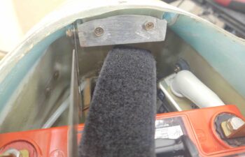
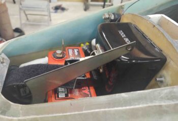
I put the battery back in the nose, because I was focusing mainly on that clearance with the hinge. I quickly realized I needed to go grab my tool box and put it back in place to check that clearance as well with my longer hinge.
To then realize further that I had some issues to resolve. My new longer hinge is over an inch too long for clearing the tool box.
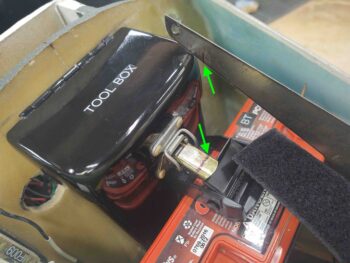
Moreover, I apparently never vetted the tool box’s clasp operation with the rather robust battery securing strap I have around the center of the battery. The clasp arm snags in opening and closing on the battery strap clasp… by about 1/8″.
Solution? You can see the line I made on the tool box clasp to simply trim it down. There’s not a ton of force required on the clasp to open or close it, so I don’t foresee any issues with cutting it a bit shorter.
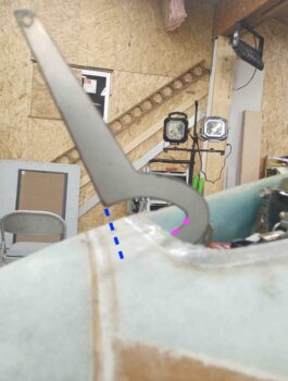
After playing around with the door and setting it where it would be in place aligned with the hinge, I quickly realized I have a hinge alignment issue. I tested it out a little with the older “wrong-angled” hinge and I don’t think it’s due to the new angled hinges, but at this point simply because the “U” part of the hinge is too big.
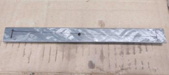
The gap between the double magenta dashes (bottom trough of “U”) and the front edge of the hatch needs to be reduce to almost nil. Moreover, the height between the front connecting edge of the hinge (top of “U”) at the blue dashed line needs to be minimized quite a bit as well, since with this current configuration the front tip of the hatch door would rest on the top of the nose (not good) versus the front lip of the nose hatch stopping the hinge travel when the door is opened fully, as in this pic.
In addition, I think moving the hinge pivot point as far forward as possible should help mitigate my nose hatch door hinge opening geometry issue.
I think I can say authoritatively I now understand why builders go with either the external CAMLOC/screw or the wire-through-embedded tube methods to secure the hatch door to the nose, because this hinge-solution is turning into quite the cluster.
So knowing I had to go back to a few different drawing boards, I called “Uncle!” for the time being on the nose hatch and went to work on the milling machine reassembly.
I started with the Y-axis gib on the saddle. I marked and drilled the 1/8″ pilot through hole to allow oil to come in from the new fitting.
Then, based off the through-hole I marked up the oil distribution channels. These will be used to spread oil fairly evenly on the mating way surfaces.
I then used the Dremel tool to cut about a 1mm deep trough along the lines.
I then pulled the X-axis gib, which is also located on the saddle, and did nearly exactly the same thing as above. Except the X-axis gib has 2 oil through-holes.
With that, the mods to all my gibs are all complete with all having much better oil distribution pathways now for far increased lubrication capabilities via the One-shot oiler system.
The current limiting factor is that my ball oil conversions via drilling and tapping aren’t going according to plan. Just not enough meat left over, so it’s proving hard to really secure the threaded push-tubing fittings into the converted ball oilers. I’ll need to make up some press-fit threaded adapters on the lathe once I complete its CNC conversion as well.
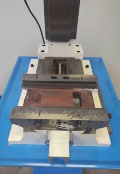
Nonetheless, I was able to get my saddle re-installed onto the mill base.
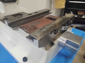
(BTW, the Y-axis gib is located where the round flat screw is located on the lower right, near the angled way… and you can see the X-axis gib screw sticking out to the right at the top of the saddle).
A closer shot. The X-axis gib is located at the top, on the aft side of the front block at the intersection of the angled way and the round bolt depression (near middle of pic).
I then cleaned up the interfacing ways/rails on the bottom of the bed and slid that extremely heavy beast into place on the saddle.
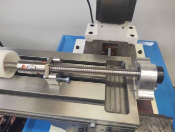
I had every intention of installing the X-axis ball screw, but then quickly realized that the configuration was wrong if I wanted the stepper motor to be mounted on the right end of the table. It’s not an insurmountable issue to mount the stepper motor on the left, but it does optimize cable routing with my CNC control box mounted on the back wall to the right of the mill as I have planned.
Going back through my emails and notes, I could see where all the pics showed the ball nut (orange spots) facing towards the end cap (both visible in pic below) vs facing away as it is here. The former equates to the stepper motor being mounted on the right, the latter –as here– requires the motor to be mounted on the left.
I contacted the notorious Dave Clements, maker of these PM-30 CNC conversion kits, and he quickly responded that he’s sending a new, correctly-oriented X-axis ball screw out to me with a shipping label to return this one. Can’t beat customer service!