
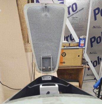
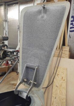
With the nose hatch door paint good and the clear coat on and intact, I mounted the door to the hinges… here’s a couple shots.
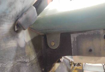
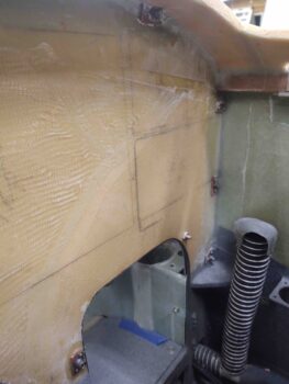
I then got busy installing a click bond with 3-plies of glass over it on the front face of F22, and a RivNut on the upper side wall (held in place by clamp) to allow me to mount Adel clamps when routing the nose hatch door latch cable.
I then carefully trimmed the nose hatch door latch pull cable to length with my Dremel tool…
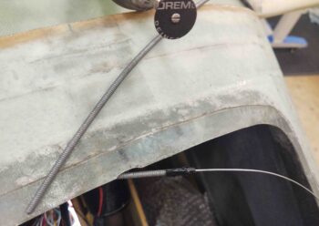
. . . routed the cable and terminated it at the door hatch latch arm.
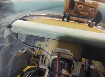
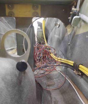
This is a view of the nose hatch latch pull handle. Pardon the bundle of wires behind the cable pull handle… that’s why I have wire labels and electrical diagrams! ha!
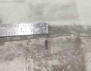
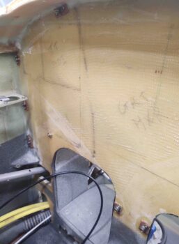
Here’s the nose hatch door and nose centerline (top) marks. The nose hatch door is latching about 1/16th to the right (left in pic). Doesn’t seem like much, but considering it skews how the nose hatch door sits in the “pocket” created by the lip and surrounding flange, I’m going to dial it in to move it back to centerline.
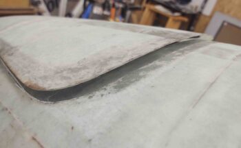
Like I mentioned before, the nice thing about this style of latch is that when you “pop the lid” it gives you a nice raised hatch door to grab ahold of to open it up.
With the nose hatch latch technically complete, I moved on to floxing in all the instrument panel securing nutplates: 10 total. The 2 nutplates on the center strut are 1/4″, while all the others are #10.
Here’s the other side. After around 6 hours cure time (fast hardener) I removed each screw, cleaned it, and then re-installed it. I didn’t want to check these floxed-in nutplates tomorrow simply to have a screw permanently floxed into it, although I did apply a thin coat of grease to all the screws before installing.
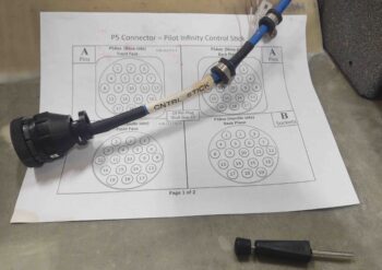
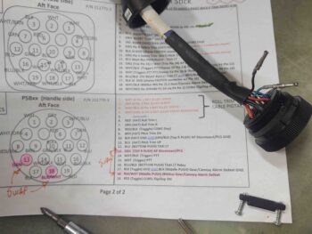
My last task of the evening was to swap out to connector wires on the control stick P5 connector to actually complete the physical swap of the autopilot disconnect and the gear/canopy alarm defeat buttons.
The diagram underneath the cable and connector is a 2-page sheet I have for each connector. The first page gives me general information about the connector.
The second page gives me specific pin-out information for each side of the connector. These things are lifesavers if kept up to date and the info is current, which is why I’m so maniacal about keeping all my wiring diagrams up to date.
Here I’ve cracked open the connector to gain access to the wires and sockets.
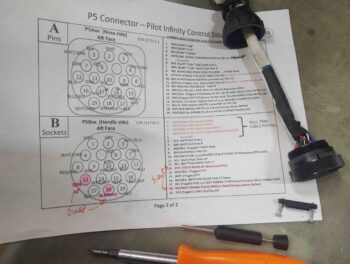
Then, using the black tool shown in the pics above, I pulled the wires/sockets I was looking for. I then swapped them out and did a continuity check on them to ensure I had them correct… and all was good. This made the swap of the AP Disconnect and Alarm Defeat buttons on the control stick officially complete.
(I also did a quick continuity check on all the other circuits as well and they all looked good).
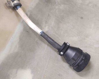
I then put it back together. It’s ready for operations!
I then packed it in for the night. I know I keep saying it, but I really am getting closer to getting that aft nose/avionics cover installed!