
I started out today by trimming the aft nose/avionics cover hinge brackets that I installed and glassed last night.
I noted that the hinge configuration worked best with both of them each mounted on the right side. It allows the left hinge to open up more fully, closer in line with the right hinge. And it allows the right hinge to better clear the electrical wire bundle traversing along the upper right side of the NG30 cover.
As I posted last night, I ensured the hinges would fit and function with the NG30 cover in place. I’m thinking that’s the first time I’ve installed the NG30 cover since the top of the nose was completed and also with the canard in place.
I was remiss in not accounting for how much G10/phenolic I had on hand, so I just ordered a big piece last night to make the hinge brackets for the cover. I need to work the hinges first before most everything else since the swing and settling-in of the aft cover into place will dictate the configuration of most of the other securing points. I’ll of course work what I can until the G10 arrives. Which may mean I get a lot of panel work done!
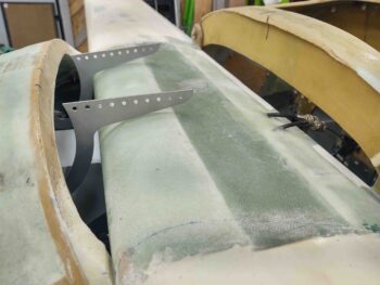
Here you can see the aft nose/avionics cover hinges saluting.
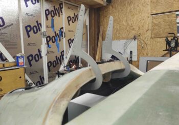
I’m pretty much done with the nose-side aft nose cover hinge brackets, except for trimming them down in size a bit now that I know I don’t need to move the hinge pivot holes.
The hinges aren’t perfectly aligned since the priority was maximized clearance with the canard on the outer edge of the hinge curve, and the top corner of the nose (cross “bridge” piece forward of canard) for the sharp corner of the hinge. There was very little wiggle room before the hinge was either scraping on the canard LE or else unable to travel forward due to snagging on the corner of the nose cross piece. Since the nose isn’t perfect in curvature, and definitely doesn’t have a uniformly curved underside, combined with my forcing an equidistant measurement from centerline, they are off from each other in max opening height and overall elevation… but I don’t see why they won’t still work as designed and I’m very pleased with how they’ve turned out so far.
I started my panel work by drilling out all the small round holes for switches, CAMLOCs, etc. Since I have 6 aft nose/avionics cover attach points across the top of the panel: 4x CAMLOCs and 2x hinge pin passthrough/threaded attach in the corner by each longeron, I figured I would drill the other panel component holes while I was in drilling mode.
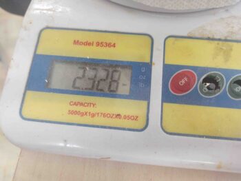
I then got busy trimming down the remaining excess weight on the aft nose/avionics cover.
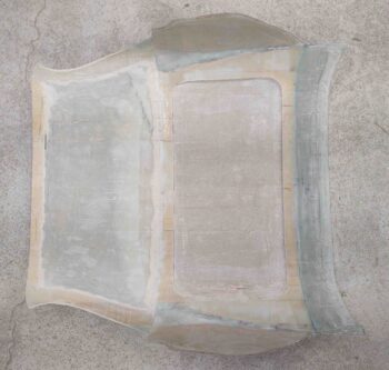
Not bad… it started at a hair under 4.1 lbs when I pulled it off the nose, and now it’s around 2.3 lbs: a 44% reduction in weight. Again, I think it will be around 2.5 lbs when installed.
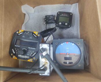
On one of my trips to the house, I stopped and grabbed a box full of goodies.
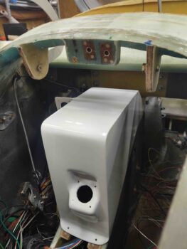
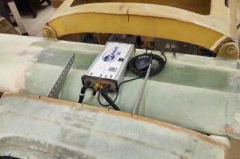
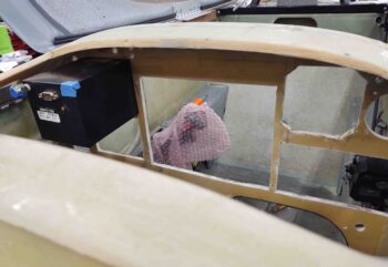
For YEARS the plan has been to mount to the Radenna SkyRadar ADS-B In Receiver on the top of the NG30 cover. But as I was looking at the cover, then the space on top of the canard, I could see no reason why not just mount it on the canard and keep the NG30 cover nice and clean.
So that’s the new plan. And here is the new mounting location for the ADS-B receiver. I already checked that all the cables will reach it just fine.
I then got back to work on the panel. I took a white paint marker and marked the interior perimeter of all the major avionics (and the ELT remote head). Also, before I removed the aluminum panel I ran the Fein saw along the inside edge of the rectangular avionics to score the face of the old panel bulkhead.
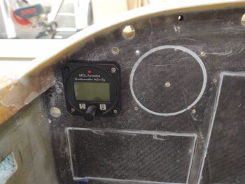
I started with the 2-1/4″ hole saw and cut out the hole for the MGL clock/timer. This one is easy because I like this guy mounted with the case on top of the panel. However, it did highlight to me that I need to make 4 more 4-40 nutplate assemblies to mount it.
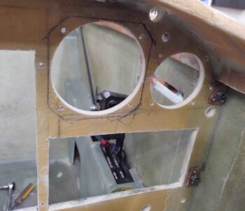
Of course I also used a 3-1/8″ hole saw to cut the bigger holes for the autopilot and ADI.
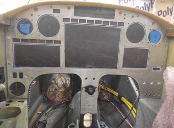
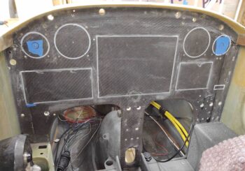
Here I’ve cut the middle row of holes: the GNS-480 GPS, HXr EFIS, and Mini-X EFIS. In addition, you can see I then mounted the Trio Autopilot.
I then marked around the Trio autopilot, essentially using it as a template.
And cut out the mark for the autopilot. I then installed the TruTrak ADI and did the same thing.
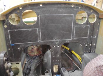
Here you can see I’ve removed the ADI and am ready to cut out the square. Hopefully this is obvious that I’m mounting these instruments straight to the back side of the aluminum panel, so they need to completely pass through the old composite panel bulkhead.
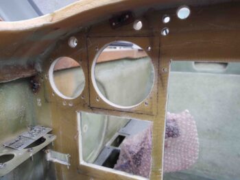
My last instrument to cut the perimeter through the old composite panel bulkhead was the vertical card compass. It sits so close to the ADI that I just cut straight through the right side of the ADI cutout to make a cutout for the compass.
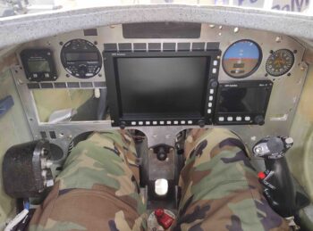
Of course I couldn’t resist climbing into the cockpit and making some airplane noises after I got the panel assembled with a good bit of instruments. I am super happy with how the panel is coming along… I really love the layout and functionality of all the components.
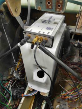
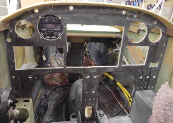
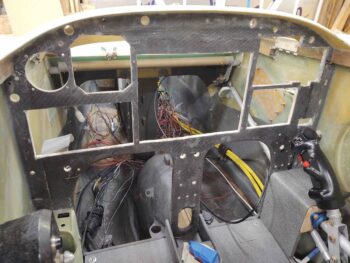
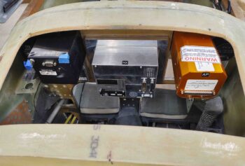
BTW, here’s a shot of the components from behind the panel… note how much access the top open area under the aft nose/avionics cover provides.
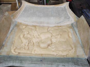
My last task for the evening was to fill the aft depression on the underside of the aft nose/avionics cover with pour foam. Surprisingly, it took me 3 whole sessions to get this area filled. I’ll trim and sand down the foam and prep it for the 1 ply of BID I plan on laying up over the areas that I essentially strip mined for weight reduction.
And with that, I’m calling it a night.