Today was huge as far as significant progress on my build.
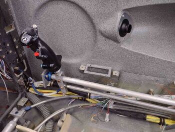
First, I started by gathering up my front control stick and right side pilot armrest to assess my control stick mounting angle. Once again, the Cozy Girrrls make extremely high quality parts, but they have the name “Cozy” in their moniker for a reason (or did, as they are now finishing up a Long-EZ).
The Long-EZ plans say to lean the control stick tube in 5° at zero degrees/neutral ailerons and install. However, with the slick Cozy’ish straddle-stylel control tube that I got from the Cozy Girrrls, it has what looks to be 12-15° slanting control stick mounting nub on the top with ailerons at neutral/0°.
I wanted to get the best angle both for flying comfort and also for left/right clearance both within the armrest, but also with the lower fuselage sidewall at full left aileron, and upper fuselage sidewall at full right aileron. I decided to go with control aileron tubes pretty much centered which gives me about 12° inboard slant on the control stick. Not too crazy really when you compare it 5°, and if it really becomes an issue I’ll just pull the control stick assembly, lop off the nub and practice my TIG welding!
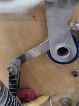
I wanted to also ensure I had at least 1/32″ clearance between the CS124 pivot and the firewall mounted bearing. This gives me about 1/8″ clearance from rod end bolt heads to current firewall, and with a 1/16″ Fiberfrax going on before the 0.025″ Titanium sheet for final firewall install configuration, I should have plenty of room.
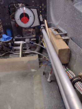
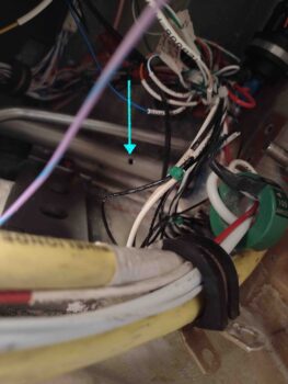
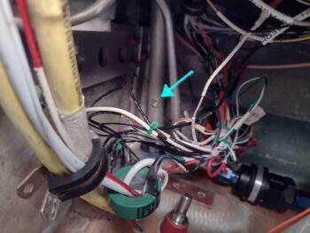
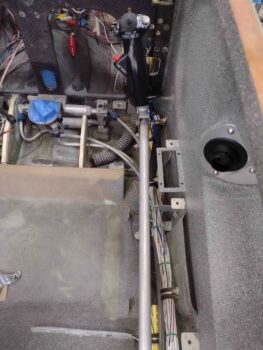
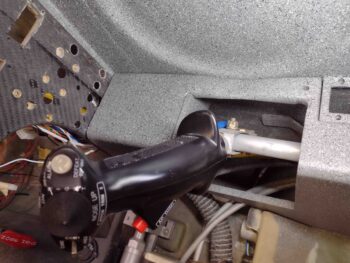
The crazy part of this adventure was getting into the very aptly named Hell Hole… boy did it live up to its namesake today!
As you can (barely) see, the CS121/CS122 pair is buried in the upper right corner.
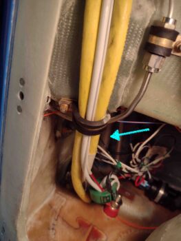
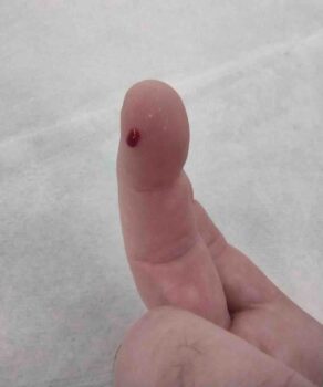
As an aside, I spent a good 15 minutes hunting down and sanding finger killers and vacuuming out the dust to avoid this… which happened mere minutes after ending my hunt for just such offending bits of glass.
I tried in vain for a good 10 minutes to get my 90° tube drill jig up there onto the aileron control tube to drill a nice centered, perpendicular hole… but I didn’t have any clearance to get a clamp up there and I couldn’t get a good seating position to get both hands up there to wrap duct tape.
After sitting there for a couple minutes pondering how to make it work, I said “screw it!” and free hand drilled it with a 10″ long #12 drill bit. After I broke through on the bottom side of the tube I did zip tie a small square to my drill bit to give me a close approximation to what 90° was.
I tried installing the plans called out AN3-11A bolt from the top side of the tube, but we all know the story: there’s just no clearance between the tube and the bottom of the CS spar. I am out of and had ordered —but not received yet— some AN3-10As so my next bolt in line was an AN3-7A. Since my install is temporary at this point since the aforementioned firewall components need to get installed, I simply put a standard nut in for the time being.
With my ailerons clamped at zero on the wings, this set my control stick at it’s new zero position as well.
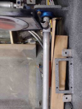
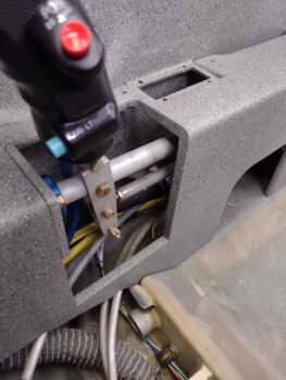
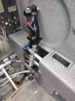
Here’s a top view of the pretty much vertically in line control tubes.
And a shot of the control tubes’ clearance within the armrest with ailerons at neutral.
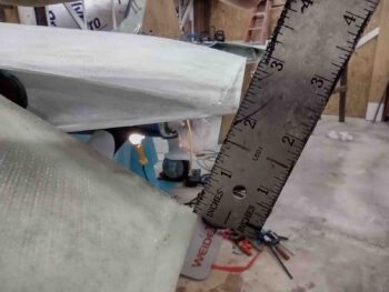
I then moved the control stick full left until the left CS128 bell crank hit the 20° up aileron hard stop.
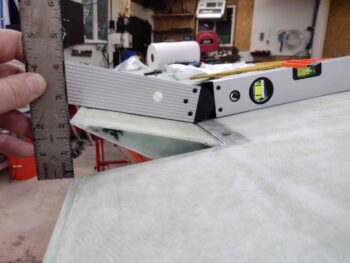
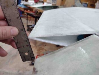
Bingo! The aileron is right at 20° up (angle finder is at 160°) and my physical gap is a hair over 2″. On the opposite right wing, the down aileron gap is over 2.1″, so looking good at the ailerons with full left stick.
And I have way too much room between bottom control stick and sidewall… it reminded me of when you attempt to barter with someone at a market in a foreign country and they accept your first offer. Doh! Could’ve been much less! Well, here, the stick could be over another good 3/8″ providing more leg clearance in the plane… but full right aileron will complete the story.
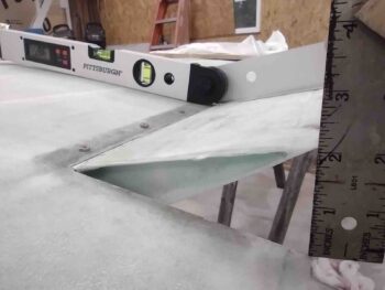
I then did the same exercise to the right: full right stick to the CS128 bell crank hard stop.
My down aileron gap on the opposite left wing is an unusually paltry —for down aileron— 2″. Good enough, but often we canardians see 2.1-2.4″ down aileron gaps. The up travel on the right aileron is about 20.4° with a 2.1″ gap between wing and aileron TEs, so I’m definitely ok here.
In fact, it’s probably good that I’m getting a bit over 20° up travel on the right because this is with the stick pegged against the sidewall. The control stick edge and CS128 bell crank hard stop both physically hit when the control stick just kisses the sidewall. Obviously during normal flying ops I’ll rarely notice these extremes.
Note how far inboard the bottom of the control stick protrudes just a bit past the armrest. Not bad at all, but this would be going into either seat cushion or my thigh a little bit. Whereas the full left aileron exercise would theoretically allow me to move the controls outboard, this is telling me that we’re in a good spot with this exact positioning, all things considering.
I’ll take it! Task complete.
I thought late yesterday that I had received my roll of UNI that I ordered from ACS, but I unwrapped the plastic and paper to reveal it was actually the roll of BID I had added as a late addition to the order the next day. Hmmm?
I checked my email and sure enough, the order with my UNI was out for delivery. So I took a good hour plus break and grabbed some food before my next endeavor on this build.
Once I got the UNI in hand, I cut Ply #1 for the right strake (sorry, still had the camera in stupid macro mode… ever since they updated my phone without permission the camera works slightly differently!). This ply of UNI is parallel with the strake leading edge.
And then ply #2, which runs parallel to aircraft center line.
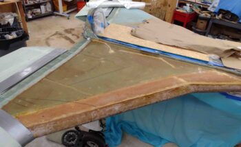
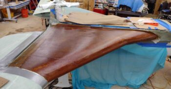
I then prepped the right strake top foam, seams and fillets with EZ Poxy micro and flox. Clearly I applied wet micro to the foam surfaces. I’m using EZ Poxy here on the right strake top layup to finish up the last bit of E-Z 84B hardener.
I laid up the first ply of UNI on the strake, with it being a bit more fiddly going on then I remembered with the strake bottom skin layups… but it ended up good.
I then laid up UNI ply #2.
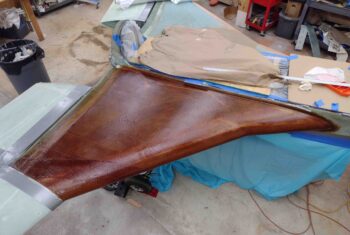
And wetted it out. EZ Poxy really does have a beautiful look to it when it goes on.
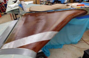
I then added the requisite ply #3, a 5″ diagonal strip of UNI. I could argue that with my OD rib not in the plans position that this isn’t doing a whole lot for me, but what the hey, it’s one ply of UNI and I threw it on there just in case!
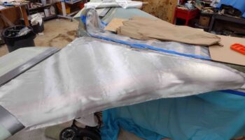
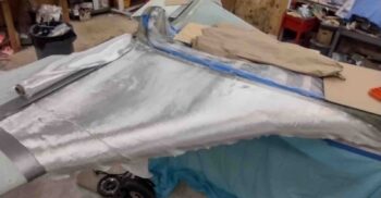
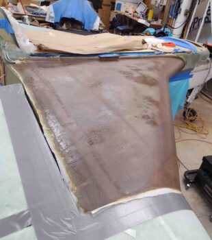
Here we have all the UNI plies laid up on the right strake top.
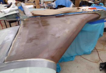
I followed a chapter out of Wayne Hicks’ build, although I don’t remember if he actually went through with it (or maybe it was Bernie Siu… who remembers these things. ha!) by adding peel ply to the entire strake top layup. I know from the bottom strake surface it took about 2 hours to sand that nasty UNI in prep for micro finishing.
Well, admittedly it took a good hour getting this somewhat wrinkled (it’s been through many moves!!) peel ply applied, wetted out, squeegeed and stippled to remove all the air I could.
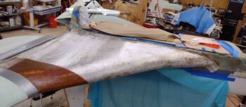
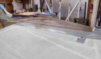
Here we have the strake leading edge with the new top glass overlapping it… which I’ll note that I am pretty darn happy with.
So that is the end of today’s adventure… that not surprisingly went well past midnight by the time I cleaned and tidied up the shop, turned out the lights and locked up. Time for a glass of red wine!


