
I started out today by pulling my table saw out from the outdoor shed and cutting some wood in prep for the the canopy install. The forecast was for afternoon thunderstorms, so I wanted to get the wood cutting out of the way, and I just made it before the rain started… by about 15 minutes.
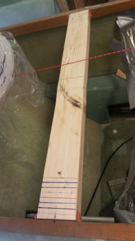
One piece that I cut was the forward canopy cross support that will both support and align the forward end of the canopy during construction of the canopy frame.
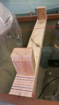
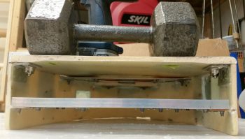
The actual final bit of supporting and aligning is done with these 2 blocks. The top, outboard edge of each block has a 1/8″ notch cut into it for the canopy bottom edge to nestle into for alignment.
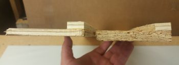
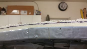
For the aft side of the canopy, I created the side rails of what will be a spreader, each of which will push out against the longeron, and concurrently the bottom inside edge of the canopy to keep it splayed out in the right configuration during glassing.
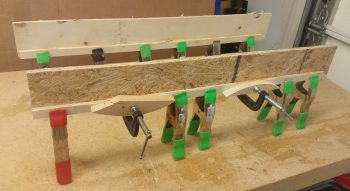
Since my longerons are a bit wider from the pilot’s seat bulkhead aft, I glued on a 0.3″ strip of wood at the top of each spreader that will be the actual contact point against the inside of canopy edge to keep the canopy sides pushed outward. This puts the canopy edge aligned with what would be the original inboard edge of the longeron, giving me (or the GIB really) about 5/8″ more canopy width internally and also creating a wider internal lip to allow for a bit wider canopy rail to interface with the longeron.
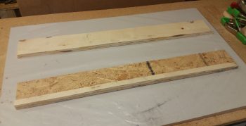
Here’s an end view of the canopy spreaders with the added 0.3″ strip at the top of each one.
I went back to my blog to refresh my memory to see how I installed the CAMLOCs when I put them in for the pilot’s seat thigh support. In my own blog I mention not having the correct rivets on hand. And I’ll be darned if I never ordered those correct rivets!! Argh!
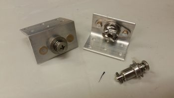
The only 1/8″ rivets I have on hand that would work in general are button head rivets, and for installing the CAMLOC receptacle brackets for the headrest cover I definitely needed countersunk head rivets. Since I have the much larger 5/32″ rivets on hand, which are fairly long as well just as a point of note, I decided to use them instead.
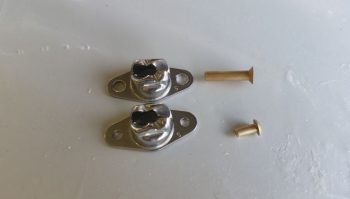
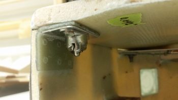
This of course meant drilling each lightweight STAINLESS STEEL CAMLOC receptacle (these are actually a SkyBolt product btw) to widen the rivet mounting holes from 1/8″ to 5/32″ diameter. In the end it really wasn’t that difficult. The only negative was that I set the 5/32″ drill bit down for a second conveniently located right next to the 11/64″ bit… which is what I of course grabbed to drill the wider rivet holes! DOH! Oh, well, a few thou more of play but they still worked fine.
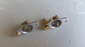
Here you can see the differences in rivet size. Of course I ended up cutting the length way down on the 5/32″ rivets.
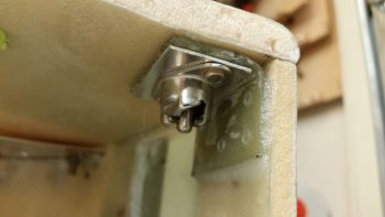
After fiddling about with getting the cover in the best spot (there will be some trimming of the cover along the edges), I prepped the lower CAMLOC brackets and floxed them into place.
Here’s the right side lower CAMLOC bracket to secure the headrest cover into place.
And the left side.
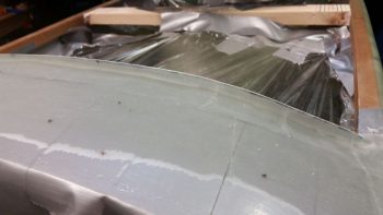
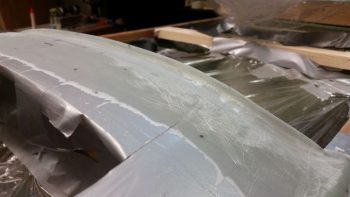
I then got to work on the glare shield. I started by pulling off the little foam wall I had built to create the raised drip (or “anti” drip I guess) edge.
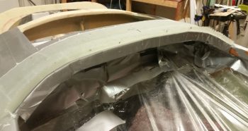
I then marked the drip edge for trimming, at about 0.35″ high.
 It’s hard to see in the pics above, but the raised drip edge still has some nasty gnarly edges from the original glassing.
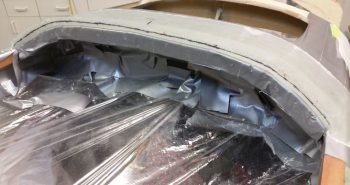
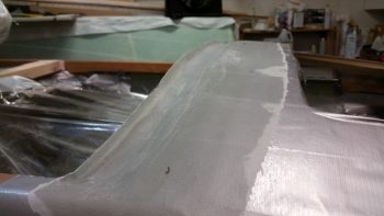
I then used the Fein saw to cut the glare shield’s raised drip edge.
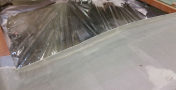
And a final couple of shots of the trimmed raised drip edge on the glare shield, after some very aggressive sanding to get the surface just forward of the drip edge to a nice smooth curve. I think once the additional plies of glass are added this area will turn out very nice!
I then made up/prepped the 2 upper CAMLOC receptacle bracket assemblies only this time I used 1/16″ thick angled aluminum for the brackets.
Here we have the GIB headrest faceplate cover held in place with the 2 lower installed CAMLOC assemblies.
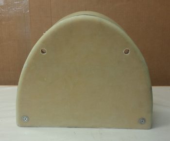
Here I’ve simply slid the top CAMLOC studs (which I will need to order longer ones for the top) in place for this pic.
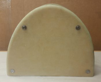
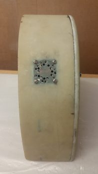
I then spent a little bit of time drilling the vent holes for the upper cooling fan (exhaust). I know the holes may look like I drilled them willy-nilly, but there is actually a pattern that follows the configuration of the fan to optimize airflow out of the headrest structure.
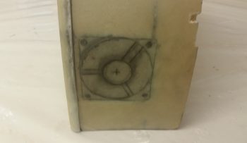
Since it was fairly late, I couldn’t fire up my Fein saw, so I’ll get to cutting out the sidewall glass for the lower intake cooling fan tomorrow. I did mark it up in prep for that.
Clearly I didn’t get the headrest structure glassed into the fuselage yet, mainly because I wanted much easier access for working both the cooling fans and the CAMLOCs attachment assemblies. I should get to glassing it in tomorrow and then pressing forward full bore on the nose and canopy build.