
Today was all about the initial big push to get the aft engine baffle templates dialed in for my engine in prep for when the inner baffle forms arrive and I get those knocked out and installed.
I started on the left side and cut Mike Beasley’s “Beasley Baffles” template at the long corner edge of the upper “shelf” section and the lower “skirt” section. I used the upper shelf section as is and trimmed it to fit.
On the lower skirt section I made a copy of the original template on a large piece of poster board and then used that to make my template on my engine.
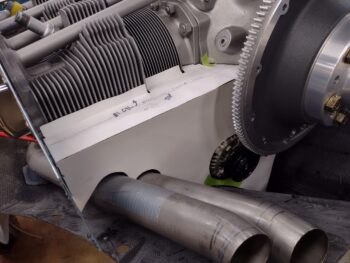
After I dialed in the left side top shelf section and the bottom skirt section, I simply taped the 2 pieces together. All in all, with the constant iterations of putting the templates in place, marking, trimming, putting back in place… rinse and repeat… it took me well over 2 hours just on that part alone.
But I am definitely much, much closer to a finished product, albeit with a myriad more tweaks and trimming left to do. This is merely the first stab at getting an initial workable template for the aft baffle segments.
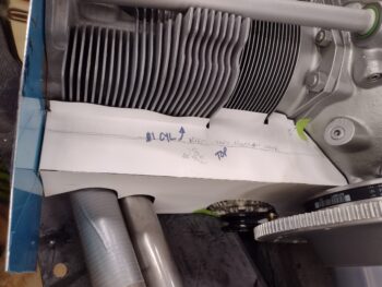
I then repeated the same thing on the right side. Again, this took a good couple of hours to do the initial skirt baffle copy and then slowly dial in the shape and form of the right aft engine baffle. Note that I actually had a little help on this side with the screw hole in the #2 cylinder head.
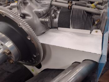
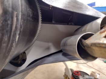
Here’s a shot of the engine aft baffle “shelf” sections. I’ve seen this baffle style in a lot of pushers where the aft corner edges of the shelves match, even though clearly the right shelf —with the cylinders positioned forward— is much wider than the left side.
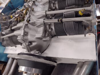
The area beneath the flywheel, around the alternator and starter, is typically much wider, deeper and bowl-shaped on other Long-EZs than the “V” shape that the Melvill cowling has… regardless, it all seems to fit so I’m happy with it.
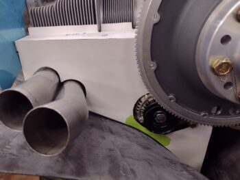
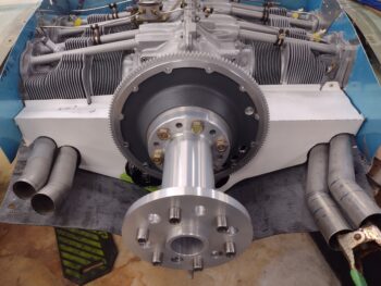
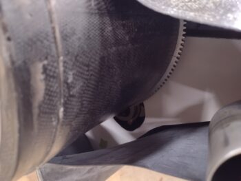
And here we have both poster board/thick paper aft baffle mockups in view. I really like the way this will look when completed. That being said, I have to note that both sets of exhaust pipes are kicked out a hair more than they will be when all the component installs are final. Thus clearly why I’m dialing these aft baffle templates in with poster board so I can tweak, modify and dial in as required.
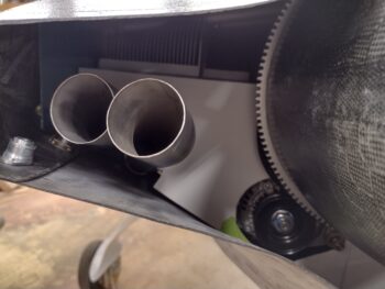
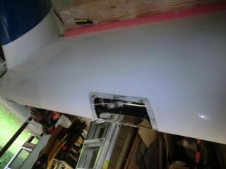
To get an idea (for me and you!) of how this will look with both the spinner flow guide and upper cowling in place, I went ahead and temporarily put both in place. As each step progresses and each task is completed on this engine area, I’m more and more pleased with how it’s all turning out. It honestly was not a fun first half of this year figuring and working it all out.
And with all that good feeling talk, I should note that I’m going to have to make a significant cowl bump on the RIGHT side bottom cowling under the horizontal elbow of the right inboard/cylinder #2 exhaust pipe. It’s just too close to the inside corner of the bottom right cowling.
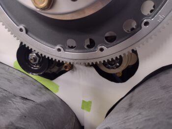
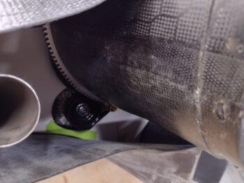
These pics give you an idea of what I’ll be looking at during pre-flight when I check out the alternator and belt on the left side and the starter on the right side. Yep, even though the cowlings are very tight around this engine, I still have good visibility to check on these components pre-flight.
I had texted Nick Ugolini earlier in the day that I was ready to discuss the wing light forms that I received from him (as well as a slew of pics). We agreed to discuss my wing light install later in the evening. Well, perfect timing on Nick’s part because he called tonight just as I was just winding down in the shop.
Nick and I were on the phone for well over an hour discussing primarily his how-to steps on installing the outboard wing landing and wig-wag lights. In addition, we spent a good little bit talking about baffling and engine cooling.
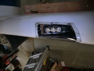
If you’re not familiar with the outboard wing leading edge lights, here’s what they look like when the install is complete:
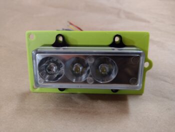
Although it was late, my curiosity got the best of me and I measured up one my AeroLEDs “Recognition/Landing Light Assemblies” to model up a light support bracket for mounting into the leading edge of the wing.
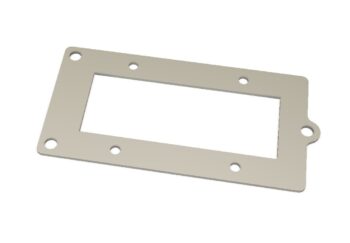
I then of course did a quick 3D print of the wing light bracket.
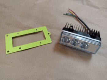
Thankfully my numbers were correct, and the light fit like a glove in the 3D printed test light bracket.
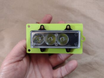
And a bit closer final look . . .
Like I said, it was late… so with an unplanned task knocked out, I hit the rack.