
Ok, another 2-day update here in this post…
I’ll start off with that I have been doing a good bit of research and final verification on my electrical system circuits and component connections, mainly in the stuff handled by the TCW Tech IBBS.
With that said, I started off today by laying protective plastic into the bird once again for a minor mess I plan to make. I then brought the Warning Annunciator Sub-panel out to the shop and temp mounted it onto the panel.
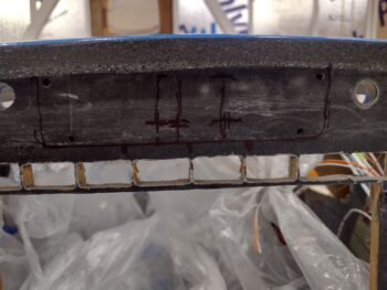
I traced around the sub-panel with a fine tip Sharpie and marked the centerline and AG6 button locations.

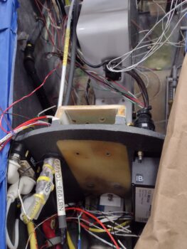
I then removed the panel and figured out where my 2 holes for wire transition through the composite panel and for the ribbon cable connectors for the AG6 annunciator button displays (pic 1). Once I got it all figured out, I drilled 2 pilot holes (pic 2).

I then used a 3/4″ hole saw to drill out the 2 holes. Thus the aforementioned mess I referred to.

Here’s a shot on the front side of the panel.

Moving on with messes… but first, a quick recap: here is a pic from over a year ago when I cut the original composite panel to allow installing my new clock/timer, which happens to moonlight as a full up mini-EFIS. I previously had a 2-1/4″ circle cutout out with the 4 corner 4-40 screws with platenuts on the back side (actually “front”) of the holes to secure the screws.
To fit the MiniUni-2 Clock/EFIS I used the top outboard screw hole as a reference for cutting out the squarish shape of the clock/EFIS as it only mounts to the aluminum panel fascia and otherwise needs clearance through the original composite panel.

Well, I left that tab uncut and now with my plastic sheets still in place for drilling the wire access through holes near top centerline of the panel for the warning annunciator sub-panel, I thought it was a good time to make another mess by eliminating this unneeded tab.
So Voila! It’s gone.

And yes, besides a fair amount of research (I did touch up paint one of the Vortilons) and planning/organizing/documenting electrical system tasks, this is it for Day 1 [which was a full entire day on the plane build].
Day 2 started out in Phil’s shop… where I RTV’d the left wing Vortilons onto the leading edge after measuring and marking the install points.

Here’s another shot of the 3 installed Vortilons on the left wing, as well as some of the finish work that Phil and Ray did on the wing top.

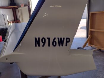
I then got busy on the N-number application on the left winglet. After measuring everything out (note the taped-in-place yardstick on the top edge of the winglet to get my reference marks) to get the N-number as close to parallel with 0 W.L. as possible, I applied the vinyl decal.

Here it is, squeegeed out with the protective paper removed.
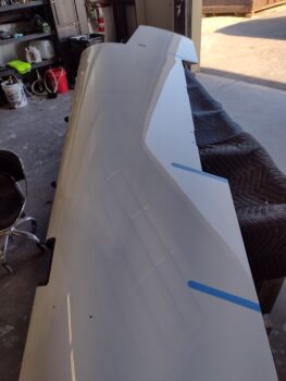
The longest and most involved task at Phil’s shop was temp mounting the wing trailing edge fences, marking their mounting flanges on tape, and then cutting the tape and getting it back on at the correct angle (I used my 3D printed jigs for the angles).
Anyway, here is the taped off base areas for the trailing edge fences. Again, the tape is to keep the ceramic coating off these areas which would make RTV’ing these fences in place —which I plan to do after 3-6 months of flying— nearly impossible due to how slick the surface is after ceramic coating.

A good bit more research when I got home, after the buffed out and ceramic coated bottom cowling, right elevator and both aft wheel pants were all put away.
I called TCW Technologies and left a message with one of their techs regarding my question on the IBBS.
In addition, you all may not know that Marco had an odd electrical mishap working on his Long-EZ in his hangar that messed up both his GRT Mini EFISs. It looks as if an errant short may have damaged them, but the more concerning issue is that both have a 1A circuit breaker to avoid just such an event. So I had a 1-hour long discussion about that and other avionics related topics with him.
One issue I’m dealing with, both with Marco’s experience (btw, he sent them both in and they are now back installed and working in his bird… but not without a pound of flesh in money for repairing them) and reading the install manual on my HXr EFIS is that it states that an on/off switch (avionics or otherwise) is preferred. Thus, I am nailing down both the possibility of adding a switch for my HXr EFIS and possibly other panel avionics. Moreover, I should note that flying back from Rough River 2023 one of Marco’s GRT screens needed to be rebooted, so it would be nice to have that capability as well… which clearly an on/off switch offers me.
There are also questions and requirements for fusing the components getting powered via the IBBS’s X-Bus (powered through and via the IBBS routinely, before any backup power function kicks in).
Finally back out in the shop I did a lot more data collection and verification on a good many electrical components. Making up a list of required wire labels, circuits and installed inline fuses.
I then wrangled the wire bundle exiting out the of the bottom hole of the Napster bulking (coming from the nose battery compartment) and secured the bundle with 2 Adel clamps. You might think this was merely a 10 minute task, but try almost an hour with getting the wires isolated, clamps sized and holes and threads cleaned up before actual install.
Part of my verification and data collection was in regards to the Warning Annunciator Sub-panel. What wires were already run? What circuits were on hand? Switches? etc.
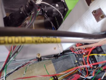
I then installed the CS6-CB onto the newly installed 6 AWG main buss to master contactor cable. The CS6-CB consists of 2 small narrow circuit boards zip tied to opposite sides of the cable that serve as an ammeter, telling me the current flow that my avionics are getting supplied as it reports on my HXr screen.
Now, it came with a nice length of thick clear heat shrink, but the issue was that it didn’t fit over the CS6 once it was zip tied into place on the cable (as if they forgot to account for the zip ties… not the yellow ones). Since the included heat shrink was on the cable, with no expediate way to remove it, I cut it lengthways and simply zip tied it into place with the yellow zip ties. That didn’t seam to cover it too well, so I unbolted the cable from the contactor and added an even bigger clear length of heat shrink and covered all of it.
BUT… after taking these pics, it just looks fugly. So I plan on removing it all, and simply using an appropriately size of black heat shrink and removing all the previous clear layers and yellow zip ties to tidy it up. No ugly components allowed!


Note the black cable in the pics above, as well as below… that is the main ground connection cable between avionics area ground buss and the negative battery terminal. Below is a general idea of how these cables will be run along the right upper corner of the NG-30 cover back to the Tri-Paragon.
More to follow as I slog forward on all this!