
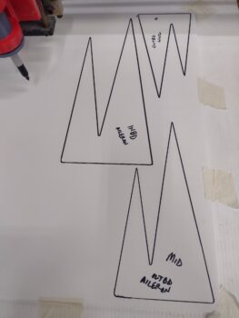
I started out this morning testing the left wing trailing edge fence angle templates which I printed 2 of last night, and one this morning.
Here’s the inboard angle template.

And the two outboard templates.

I then finalized my CAD drawings for the trailing edge fences, based on Klaus Savier’s dimensions that he recommends.
I then prepped the plasma cutting table to temporarily convert it to a plotting table.
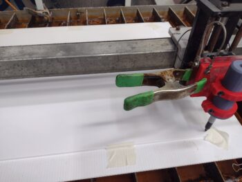
And plotted out the 3 wing trailing edge fences.
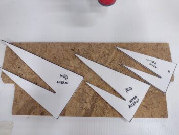
I then cut out the trailing edge fences. These will be used to check fit and cutout the actual 1/4″ PVC foam fences for each wing.
From this point on I focused on the right wing, since I’m taking it to Phil’s shop tomorrow for him to sand and buff out.
It was time for the test fit on the right the wing. Here are the outboard foamboard mockups.

And the inboard foam trailing edge fence mockup (pic 1), and all of them together in a group shot (pic 2).
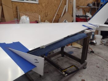
The foamboard mockups really helped in marking the bottom side of the wing where the mounting base flanges will get laid up. I then taped up the fence locations on the trailing edge —on both top and bottom of the wing— in prep for layups.

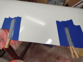
Since I’m a cheap scrounge, and I want these things as light as I can possibly make them, I’m using one ply of UNI (from scraps) and one ply of BID (off the roll) for my mounting base layups. After “pre-pregging” the layups in plastic, I then laid them up first on the inboard side (pic 1) and the outboard side (pic 2).
Since the layups are one piece at an angle, there is an overhang at the trailing edge on the inboard side, which I clamped with clothespins.

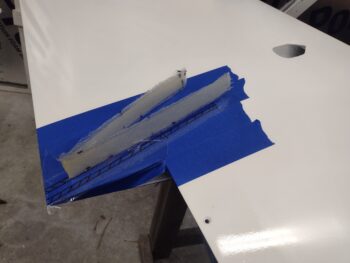
A few hours later (I used fast hardener + heat lamps) they were cured. So I pulled the peel ply and pulled the mounting bases off the wing. Here we have all of them (pic 1) and the outboard side (pic 2).


And a closer up shot of the inboard side.
A big reason I wanted to glass the mounting bases by themselves starting out, was to not have any struggle removing them after they cured…. since my wings are painted I don’t want to have to pry to get these darn things off as I most certainly would if I had glassed the fences in situ with the bases.
I then cut the excess trailing edge overhang off before taping the mounting flange bases back onto the wing, again both top and bottom.


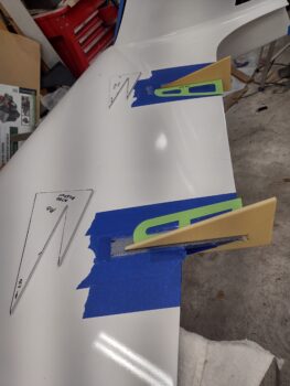
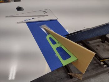
I did a final check with with posterboard mockups, annotating any gaps or angles that needed fine tuning as these will be used as the templates to cut out the 1/4″ PVC foam fences (BTW, I weighed a square inch piece of foam and it didn’t move the scale up even to 1 gram!).

Checking the inboard posterboard fence mockup…

I then cut out all the right wing trailing edge fences out of 1/4″ PVC foam sheet and test fitted them into place on the wing.
Here we have the outboard two fences.
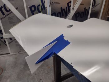
And the final test fit of the inboard TE fence (pic 1) before I micro’d it into place (pic 2).
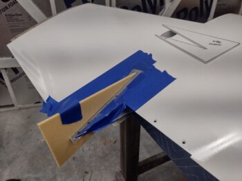
And the same on the outboard fences, test fitted first (pic 1) and then micro’d into place (I used a dab of 5 min glue on all the tips to secure them into place both to ensure their placement and to eliminate any minor gaps).


I then spent a good 45 minutes getting them aligned as vertically as possible (as in 90° to the trailing edge) which proved a bit challenging because pulling the top or bottom over to vertical could result in the entire fence being pulled in that direction. But a slight bit of patience and persistence won out.
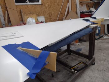
And with that, I left them to cure overnight. I’ll shape and glass (probably carbon fiber) them later, I just wanted to get this initial step done so I can finish them off the wing, then paint them, and get them mounted on the wing before Phil and team ceramic coats it (obviously after sanding and buffing out).
Needless to say, it was a long day and night as I didn’t finish until 3am in the morning. But it had to be done to get this wing delivered to Phil ASAP.
Pressing forward!