
Before I get into the specific subsystem wiring pages that I’ve completed over the past several days, I wanted to explain my requirement for creating subsystem diagrams for my Wire Book. Actually, in the spirit of efficiency, and because I think he explains it much more eloquently than I can, I blatantly stole an entry off of Nick Ugolini’s blog that helps expound upon the reasoning of why subsystem diagrams are invaluable tools to have in one’s toolkit when dealing with repairing, upgrading, troubleshooting and diagnosing electrical systems. Here’s Nick’s sage advice:
The wiring diagrams are absolutely CRITICAL to long term maintenance of the plane and they need to be as complete and clear as possible. After flying these planes for years, I find most of the maintenance issues in the future will mainly be wiring problems. Fixing a screw, bushing or engine component is quick and easy. Finding out why a light or radio stops working is really tough and almost impossible without a well-documented wiring schematic. The type of connectors, switches, plugs, type of crimper used, wire, etc should be of the highest quality possible, because it will bite you in the butt if you don’t pay really close attending to this critical aspect of the plane. Of all the work I am doing on the plane, I approach this area with the greatest concern and closest attention to detail possible. This is why it takes so much time and effort. I spent 3 hrs yesterday working on just 4 pages of wiring and I am still not done. I will probably have 30 or 40 drawings.
Some people approach the electrical draw from the aspect that you should put everything in an area on one page. An example is the power system should show all components and where they all go (charging, starting, lights, lines to the radios, etc). This is great for wiring the plane, but doesn’t help as much when you are trouble shooting a sub area of the larger system. Let’s say you are only working on the alternator part of this system.
I like drawing the areas out in sub systems. The alternator system is drawn separately from the starting system or the ignition system. In the future when you are trouble shooting problems with the charging system, it is MUCH easier to look at just the system of interest and visually see what is going on. You don’t have to separate it from a larger drawing with lots of other stuff on it. It makes wiring the plane more of a pain but is much easier to trace wires.
Anyone can wire a plane… it is not rocket science and is fairly easy to do. Run a wire from A to B and you are done. Easy. I have seen so many planes (certified and experimental) where if you ask the owner for a wiring diagram, you’ll get a blank stare. I have seen very few wiring diagrams and they were by obsessive compulsive engineer types who really knew the value of having one. Most builders just wing it.
-Nick Ugolini
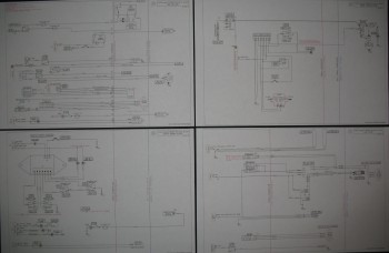
So, with much agreement and in the spirit of Nick’s words, I’m pushing on in my attempt to complete these subsystem wiring diagram pages for my Wire Book. Since my last post on electrical diagrams I’ve completed the Fuel System, Alarm & Warning Systems, Starting System, and Long Wire Runs wiring diagrams.
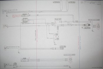
Here is the fuel subsystem wiring diagram.
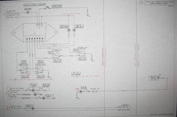
And here is the alarm & warning subsystems diagram.
I apologize if the pages look a little slanted, because they are. I’m using a Brother printer that is supposed to print 11×17 inch pages, and technically it does do that. However, it just doesn’t print the pages straight… or it does rarely let’s say. It sucks, but it was the only one I could grab in my limited time in the States before heading to the Middle East.
BTW, the long wiring runs is nothing more than a pictorial list of all the wiring runs between the nose/instrument panel area and the hell hole/firewall area so I can account for the amount of long wire purchases I may need to make if I don’t already have enough wire on hand.
Below is the updated list that I shared last week (again, green denotes completed or mature, yellow is currently being worked):
Z. Z-13/8 Electrical System
– Switch Configuration
1. Panel Components
2. Radio & audio system
3. Main Bus
4. Batt Bus
5. E-Bus
6. Nose Gear
7. Pitch & Roll Trim Systems
8. Lights: LDG, TAXI, NAV, STROBE
9. Engine Info Management
10. Fuel System
11. Cockpit Lighting
12. Landing Brake
13. Throttle Switches
14. Control Stick Wiring
15. Integrated Back-up Battery System
16. Alarm & Warning Systems
17. Charging System
18. Heater System
19. Electronic Ignition
20. P-Mag Ignition
21. Component Interconnects
22. Starting System
23. Panel, Battery & Avionics Grounds
24. Cockpit, Firewall & Engine Grounds
25. Heated Pitot Tube Wiring
26. Trio Autopilot
30. Long Wire Runs