
Ok sports fans… I’ve knocked off a huge milestone in regards to the electrical system and instrument panel install.
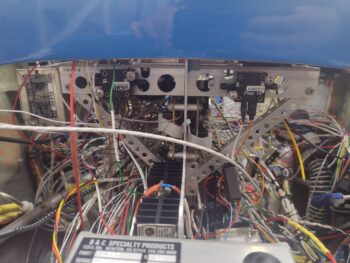
In prep of installing the Tri-Paragon top shelf, I spent the first 75% of my day finalizing both ground and power bus connections to get nearly all the open, unconnected wires routed and terminated to their final points. That being said, the primary G4 ground buss was the most difficult and time-consuming of all the busses to finalize the wiring to simply due to the limited access and position of this ‘Forest of Tabs.’
Part of my prerequisite tasks was doing the initial power and control wiring of the Video Camera MUX (MX) including the final 2 wires terminated into the P5 connector (throttle handle cable) to allow the camera fwd/rev cycling function. No pic of this and of course all the final video cameras’ wiring and MX unit mounting still upcoming.
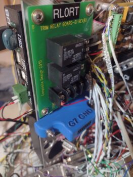
Another task was wiring up the Roll Trim Relay Board that is located on the top aft right vertical plate of the Tri-Paragon. Since it’s physically covered behind a wall of wires currently, I’m including a much cleaner pic of that component here… but it is officially now completely wired and installed.
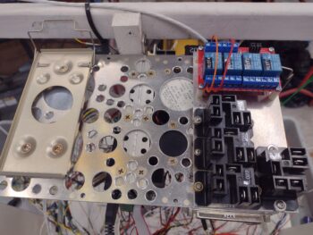
 Finally, very late in the evening, I got the Tri-Paragon top shelf installed. I realized I should have gotten a pic of it before I mounted the Trig TY-91 COM 2 and GRT AHRS atop of it, so here’s a “stock” photo of that when it was still in the panel mock-up frame (note the relay deck has all 4 of the larger capacity relays [black] installed, where I’m only running half of that complement until I may need more).
 From the left side of the top shelf we again have the Trig COM 2 radio, which I verified I can remove from its snap-in base if required. Note the rather robust D-Sub connector looking protrusion attached to the radio unit, which is the GRT adapter that allows a remote control interface of this radio via the HXr EFIS.
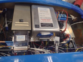
The top edge of that same D-Sub adapter device can be seen in the lower right corner of this pic on Trig TT-22 transponder, attached hanging ‘sideways’ on the right side of the top shelf. Moreover, just inboard of the transponder’s D-Sub interface adapter is the attached transponder antenna cable connector, which I quickly threaded on to ensure that the length was good for attachment… thankfully it was.
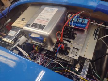 Note just inboard of the transponder antenna connector and below the aft edge of the relay deck is a 37-position D-Sub connector, horizontally mounted. This is the J4 connector (now) prewired for interfaces (minus power & ground) to the GRT HXr EFIS. Below J4, inboard/adjacent to the antenna connector is a vertically mounted 15-position D-Sub connector (J3) that is also pre-wired for the GRT Mini-X EFIS (this final wiring on both of them occurring over the last couple of days).
On the right side of the top shelf is the relay deck, with the 2 of the 4 relays on the integrated board on the front side of the shelf (blue) wired up to handle the JB Wilco warning module to throttle handle micro-switch to canopy latch handle lock micro-switch to AG6 warning annunciator interfaces. The 2 larger capacity (black) relays in the middle and aft positions on the shelf are the standard install (as mentioned above) with a capacity to add up to 2 more of these relays if/when they might be needed. The aft relay with wires installed is Relay #21, which handles the power switching between Cabin Heat and the StarLink antenna (more to discuss later on with StarLink).
Obviously the main attraction in this ensemble is the center-mounted GRT AHRS (Attitude Heading Reference System) for the GRT HXr EFIS display. The mostly wired D-Sub connector is in place, with still just a few more wires from its magnetometer to be terminated to be complete. Not surprisingly, the forward AHRS box screws are a complete bear to get installed, and I still have to finish the left front screw install before I can call the physical AHRS installation 100% complete. That being said, it’s not like these components need to be removed hardly ever, so the tight fit is just about perfect in my opinion to minimize component footprints in this tight avionics bay.
 Also note the antenna cable test connection on the Trig TY-91 COM 2 radio. This will require a bit more creative routing and machinations once the GNS-480 GPS and Trio autopilot are installed, but I think we’ll be able the thread that needle to get ‘er done.
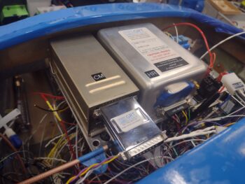
In my removal/reinstall check on the COM 2 radio I had forgot to replace the D-Sub connector in the pic above, so in my final pic of the populated Tri-Paragon top shelf (for this blog post) I added it back into place. This D-Sub connector will also get a handful more wires terminated into it coming from both the Dynon Intercom and COM1↔COM2 switching relay #9 (the photo-bombing J21B connector in front of the AHRS goes to SD-8 & E-Bus-only switch #3 on the Warning Annunciator Sub-panel, due to have its other side connector wired up in the next day or two).
 Finally, below is the front side lip of the installed Tri-Paragon top shelf, replete with 2 of the 3 airspeed switches installed… airspeed switch #1 is on the right side (left in pic) and only accessible for adjustment by temporarily removing the transponder unit. Airspeed switch #1 (again, not visible) handles the fast/slow trim response based on airspeed (~100 kt = transition). Airspeed switch #2 on the left side in pic handles both the lower speed requirement to deploy the flip-down taxi light on the nose, and any low speed alarm inputs (i.e. alarm if low speed and nose gear not down).
 Airspeed #3 on right side of pic prohibits powering on the heated pitot tube below 70 knots. Both airspeed switches #2 and #3 are wired, while airspeed switch #1’s wires are literally an inch too short to connect (due to moving it from the very right front edge of the shelf lip to midpoint right side of shelf due to clearance issues in relocating the transponder from the right top of the shelf to hanging off the right side). This is a perfect example of minor mods and changes resulting in adding 45 minutes or more of work to add/shorten/splice/re-terminate wires, etc. in dealing with unintended consequences of such changes.
Speaking of changes, I had 3 power wires to terminate onto the Main Power Bus that couldn’t reach since they simply weren’t long enough until the top shelf was installed into its final position. Even then, I had to physically swap Main Bus attach points on 2 of the 3 wires since they just couldn’t reach their originally ID’d fuse connection tabs. This resulted in relabeling both the wires and of course in the wiring docs, let alone pulling those damn wire connectors off the bus tabs… which is a small miracle for each one in and of itself. Confirming that no good deed goes unpunished!
Still, with all that being said… I’M PUSHING FORWARD!