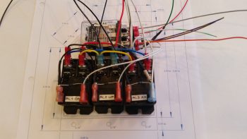
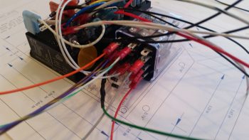
Today I finished wiring all that I could on the Nose Gear Relay Control Unit (RCU). My first task of course was to trim the lengths of the cross connect wires to the outboard relays (#1 & #3). I then re-terminated the wires with new red FASTON terminals and double checked that all was good with those.
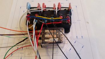
I then started cross-connecting wires from the 3 lower relays (black) to the top AEX relay (clear). One of the big challenges, which I think is a bit analogous to solving a puzzle, is to take the logical wiring diagram on paper and determine how the wires and components actually hook together in real life.
What looks like a long wire on the page can of course be no wire and simply a lead to a diode or resistor. Such is the case with the RXEF250 Minifuse that looks like a brown wafer overhanging along the top side of relay #3. Although on the diagram this shows up in the middle of wire run, in fact this Minifuse IS the wire run. The diodes at the bottom of the relay connections in the pic below is also pretty much the same way. On the diagram it looks like 3 diodes suspended mid-point in wire runs, when again they are the wire runs, all starting out at the AEX relay coil’s negative post. Out of 3 diodes hooked to the coil post, only one them is physical attached to a wire, while the flyback diode is terminated with the positive power wire, and one is simply a loner heading off by itself to a Common terminal.
The wires going every which a way again will get corralled, secured and terminated into the 19-pin AMP CPC connector.
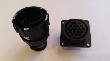
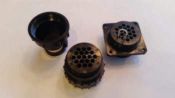
Speaking of connector, here is the AMP CPC connector for the gear RCU.
And a shot of the aft side of each connector half.
Besides physically mounting the relays, double checking the wire terminations & cross connects are correct and the terminals are attached tightly, the only thing left to do is to cut the wires to length and terminate the ends to fit into the connector. Thus, on to wiring the AEM!

