
Over the past couple of days I’ve been designing what I have come to term the Relay Control Unit (RCU) box in CAD [prior to this multi-day endeavor I spent a day and a half rewriting & reconfiguring John York’s CSA article on installing FeatherLite’s strake & strake leading edge kit specific to my build, and adding in all my past strake construction notes from Mike Beasley, Bernie Siu, Wayne Hicks, Dave Berenholtz … just to name a few].
With the incorporation of Marc Zeitlin’s new wiring for the nose gear Auto Extension System (AEX), which is essentially a redesign of Jack Wilhelmson’s entire electrical scheme for the nose gear, I wanted to get this new system as organized and compartmentalized as possible. In short, I wanted the rats’ nest of wires gone and out of my nose compartment.
Now, the 3 main components making up my new electric nose gear system is still Jack’s electric nose gear actuator at it’s core, with the actuator motor and limit switches all tucked away under the NG30 cover. The wiring exits the NG30 cover via a 14-pin AMP CPC connector and heads in two directions: 1) the new Relay Control Unit (RCU) that will reside on the left, aft side of the Napster bulkhead, and 2) the new Auto Extension Module (AEM) which is simply a replacement unit for Jack’s AEX box. The AEM will sit in the same spot on the front CL of F22 in the top, aft notch in the NG30 cover. The RCU will tie into the system via a 19-pin AMP CPC connector while the AEM will be connected via a 15-pin DSub connector. Beside the larger backup battery and laser altimeter, there are minor few connections to the Triparagon, P4 Throttle Connector, and panel switches. But for the most part, the lion’s share of the actual nose gear electrical system is contained within 3 major components: NG30, RCU & AEM.
I was drawing up a version of the box I wanted in my antiquated TurboCad system, when in a discussion with Marco he graciously offered to 3D print the boxes for me (maybe not quite understanding that my CAD kung fu wasn’t up to par with his!). He had to redraw my neanderthal CAD drawings into Fusion360 but in the end came up with the awesome box rendering you see below (note: the angled corner is the top left box corner and is specifically shaped to allow it to fit with the curvature of the Long-EZ’s nose at its install point).
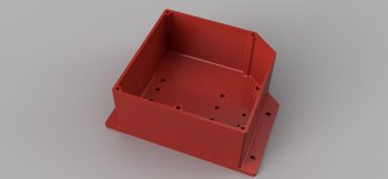
After some further discussion we came up with the lid design that will also be the attach point for the AMP CPC connector, since –YES– space is tight!

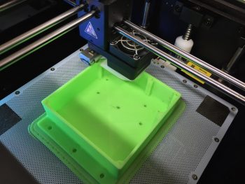
After confirming the myriad of little details on this box, Marco pulled the trigger and made our RCU box collaboration a reality. Pretty cool, eh?!
With the RCU box design complete and construction underway, I then got to work on designing the AEM box.