
This blog post covers the past few days…. of course I have a myriad of things going on to get this wiring finished.
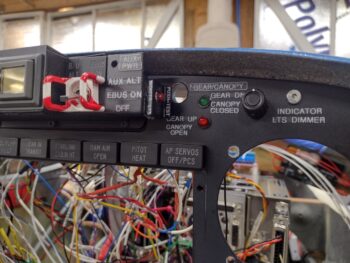
Not pictured is the completed wiring for all the top row indicator lights over the GRT HXr EFIS, including both the dimmer and the Push-to-Test circuits.
Another notable task that I completed was the installation of the green and red LED lights that make up the warning ⇔ all-is-well output of the JB Wilco canopy/gear warning system. Looks pretty easy by simply installing 2 LEDs into the instrument panel with preexisting holes, eh?
Yeah, think again buster! Untangling the LED light leads out of the quagmire of wires led to my breaking a lead off each one… which then of course required reinstalling and soldering in new LEDs. Yep, another 15 minute task that ended up taking 2 hours! (sigh).
 Over on the left side of the Tri-Paragon, or just adjacent to it to be specific, I drilled out the 2 remaining holes in the nose wheel cover and mounted the GRT Mini-X and the MiniUni2 EFIS OAT probes near the already mounted GRT HXr OAT probe. After these probes were physically inserted into their respective holes, I then applied silicone RTV to secure them in place.
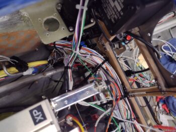
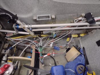
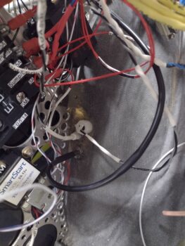 I also no-kidding finalized the top P5A connector install by tightening up the cable clamp backshell and installing the cable clamp with screws. I then finalized the control stick cable side (P5B) by threading and locking it into place. Note also the cable management that I started in earnest to get the wiring wrangled and ran as neatly as possible.
 In prep for cleaning up and securing the wires in the center area of the panel, before installing the Mini-X EFIS, I thought it a good idea to do the final and routing and termination of the center post dimmers. Thus, I trimmed the 5-wire cable on the left side to allow me to test the left side fuel site gage lights and the video cameras leads.
The strake baggage and fuel site gage lights are working fine for both left and right sides, however, I found an issue with one of the 3 video camera wires not having continuity when I checked them. I am currently in the data collection and planning process on just how to fix that one video camera wire on the left side (I haven’t checked the right fuel site gage video camera leads yet).
Moreover, not shown in the pic above of the wire management on the upper right side of the panel was the lower right side where I did the final routing and securing of the aft-heading intercom wires. To be clear, these wires are secured forward of the instrument panel bulkhead, but not yet on the aft side.
I then started the initial prep, organization and mapping out of all the wires on the Dynon intercom (anodized gold box in middle).
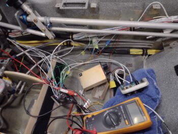 Here we are a number of hours later, with a good half of the intercom’s shielded wires’ ground pigtails reconnected/solder spliced back together. I also had to add in wire segments for 2 of the BOSE LEMO connector wires for them to be long enough to allow the headset jack bracket (black, upper right corner) to be installed soon.
 There are some wiring connection questions I have on the intercom as I reconstruct the splitting of the D-Sub wiring to allow physically removing the unit during right armrest/sidewall final construction, cockpit paint, etc…. so I grabbed the installation manual and will do some final assessments tonight before pressing forward on the intercom wiring tomorrow.