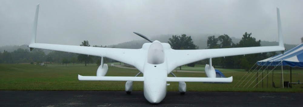
Today I didn’t get any shop work completed. I had planned on organizing & cleaning the shop a bit, and then getting the fuselage mounted on the dolly, but ended up working on the electrical system for about a total of 6 hours.
Although I didn’t add it to my log entry, I had actually spent a couple of hours Saturday diagraming out the circuit for my canopy & gear warning module. I thought I was looking for a DPDT microswitch to match the one Jack had mounted on one side of the gear actuator housing for the down limiter. The other side only has a single switch. I even sent Jack an email asking for the part number, since all the info for the microswitches were hidden from me on account of how they were mounted with the nomenclature, etc. facing the mounting flange. I didn’t want to move these suckers unless absolutely necessary since they’re “factory” set initially for the correct up & down limits.
Well, right before I left the house for the evening I took a much closer look to see what type of roller the microswitch had and the length of the lever arm. Upon closer inspection I realize it had two rollers?? Wait a minute! This wasn’t one switch! It was two switches stacked one over the other! Doh! I remembered I had a microswitch included in my accessories for the speed brake, which I also bought from Jack. I pulled that switch out, saw that it was the same switch as those mounted on the nose gear actuator, and so was able to get the manufacturer and part number off of that one. I then quickly sent Jack an email saying that I apparently need glasses and to disregard previous transmission! All of this hassle for a $3 switch! BTW, the switch is an Omron SS-10GL2T.
With the switch issue settled yesterday, and with the added wiring the new switch circuit will add, I was armed with the info I needed to order a new 14-pin AMP CPC connector from Mouser. I assembled my order which included a whole lot more pins & sockets, a pin/socket removal tool and of course the Omron microswitches.
I then turned my sights on a developing order that I had with Aircraft Spruce. I’ve been assembling this order over the past couple of weeks and wanted to get to a point where I felt I wasn’t missing anything important, like the quart of fast MGS hardener and 1″ peel ply tape that I added just prior to hitting the “submit order” button. The order includes a lot of odd n’ end fasteners & hardware for mounting electrical components, etc. in the nose. Of course, as luck would have it (as it always does!), a few hours after submitting the order I ran across EZ Point studs on Joe Carragio’s website while doing some research. They’re a bit pricey, but I know of a few places where I definitely want to incorporate these. Thanks Joe, I’ll add them to the list!
I then spent a few hours on virtually organizing the components of my electrical system. Yes, in true neanderthal fashion I pulled them all out, traced their profile on a sheet of graph paper, and then identified which bus they were wired to, and looked at the length & destinations of the wire runs. Again, since so much of this business occurs in the nose, and that’s what I’ll be building next, I don’t mind taking a few hours to get better educated on just what the nose will house before I start building it.
I made a number of annotations and tweaked/swapped/modified a number of other circuit connections simple based on location of component and the ease/requirement of access. The bottom line is that I want the guts of my electrical system to be as optimized, organized, clean, and lightweight as possible. I don’t want a rats nest of wires that looks like the cable monster puked in the nose of my airplane and then merely shut the lid to hide the hideousness of it all!
In addition to the aesthetics of the system, I want my electrical wiring to be practical in that the configuration of it all minimizes head-scratching during future troubleshooting or component additions, and even more importantly that the RF noise is mitigated to the maximum extent possible.
After creating a ton more notes, and figuring out some important electrical system design info and component placement, my final official act of the evening was deciding that a 14-gang fuse holder would be the right size for my E-Bus. Thus, I pulled the trigger on that as well and ordered one.
So although I have no sexy build pictures to post, I did get a ton of stuff sorted through and a lot accomplished. And I got three separate orders in on various in-depth, technical stuff I need for this build. Not a bad day for the build I would say.
