Over the past week I’ve continued on in my quest to complete all my wiring diagram pages for my wiring book before I leave the Middle East here within about 6 weeks! Once I return to the states, pull my Long-EZ build out of stasis, and start sniffing epoxy fumes again I won’t have the forced luxury of time (unless I take time off from actual building) to get down into the weeds of each subsystem–electrical & otherwise–that I’ve been able to do while separated from my actual project.
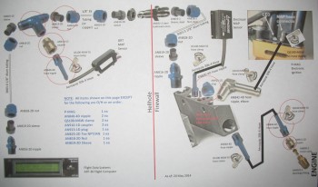
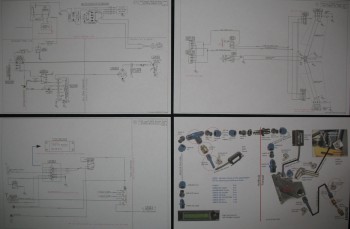
Over the past week I’ve completed the Integrated Back-up Battery System (IBBS), the Charging System, and the Landing/Taxi/Nav/Strobe/Wigwag Lights System electrical diagrams. Also, within hours of posting last week’s MAP & Vacuum system diagram, I found during a relook at the installation instructions that my GRT MAP Sensor was mounted on the wrong side of the firewall: the hot side. Unlike the Electroair MAP sensor, which is fine on the hot side of the firewall (and that’s exactly where the builder is told to install it), the GRT MAP sensor must be on the cold side of the firewall. Although I had ordered the majority of the connectors, I found during my redesign that I would still use all that I ordered, so for the project manager in me it felt good to know I hadn’t wasted any (more!) money on the stuff I did order. Like last week, in the pic below I show the 3 newly completed wiring diagrams and my updated hack Manifold Pressure system PowerPoint diagram.
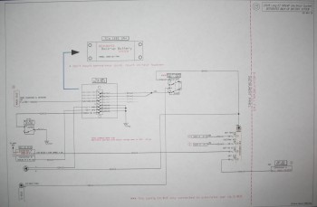
Below is a shot of my Integrated Back-up Battery System (IBBS) wiring diagram page. Note that TCW’s new 3AH IBBS is the backbone of my back-up battery system. Also, a long time issue that I had was exactly how to wire up my panel components to have them on back-up power during engine starting (thus not having to power them down during start), but also provide current protection and the ability to switch them between IBBS power and E-bus power at will. I guess this is the power behind subsystem diagrams, because after drawing it all out, reviewing the install manual & my past communications with Bob at TCW, I was able to see that I needed to create another mini-buss to solve my issue. The new mini-buss is a 4-gang ATC fuse holder ($10 off eBay with shipping!) and is exactly the same make as my other buses. I call the new mini-buss my Extended Buss, or X-Bus for short. The X-Bus works perfectly in allowing me to fulfill all my design criteria for my IBBS:
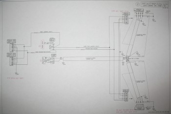
Here’s a shot of my Landing/Taxi/Nav/Strobe/Wigwag Lights System wiring schematic:
Below is the updated list that I shared last week (again, green denotes completed or mature, yellow is currently being worked):
Z. Z-13/8 Electrical System
– Switch Configuration
1. Panel Components
2. Radio & audio system
3. Main Bus
4. Batt Bus
5. E-Bus
6. Nose Gear
7. Pitch & Roll Trim Systems
8. Lights: LDG, TAXI, NAV, STROBE
9. Engine Info Management
10. Fuel System
11. Cockpit Lighting
12. Landing Brake
13. Throttle Switches
14. Control Stick Wiring
15. Integrated Back-up Battery System
16. Alarm & Warning Systems
17. Charging System
18. Heater System
19. Electronic Ignition
20. P-Mag Ignition
21. Component Interconnects
22. Starting System
And finally, here’s another shot of my upgraded Manifold Pressure system design: