
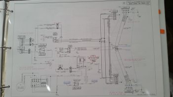
Last night I diagrammed out the 8-position DPDT relay required for the new taxi light servo. Besides adding the relay into the mix on the Lights wiring diagram page, I also updated the wire depictions from the switch to the landing light to better highlight the shielded cable. I also added in the J0 & J7 connectors.
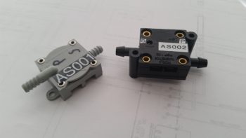
Today was all about the incorporation of airspeed switches, of which I have 3:
- AS001 – 100 knot exclusively switching trim fast⇔slow to provide faster trim response at slow speeds and minute trim changes at high speeds.
- AS002 – 70 knot for low speed warning (AG6), RAM air open warning (AG6) and taxi light deployment, all occurring below 70 knots.
- AS003 – Exclusively for heated pitot tube shutoff below 40 knots. This is a safety feature of course since I have an extremely high heat producing element in the nose of a plastic airplane that absolutely must be off when the plane is not moving.
The speeds may seem a bit generic right now, but remember these are simply target speeds and are totally adjustable. I’ll of course dial them in once the plane is flying. Also, a point of note is that none of the items controlled or reported on by these airspeed switches are actual flight control components. If the trim airspeed switch dies, then I’ll simply control the plane with a higher or lower than optimum sensitivity on the trim, or simply sans trim…. a pain yes, but a safety of flight issue? no.
The above all being stated, I realized this weekend that I had a significant issue with my airspeed switches: I just had no idea how to wire these guys up!! They seem simple enough in theory, and are right there for the purchasing at Aircraft Spruce… so what’s the big deal? Well, at the bottom of the scant bit of info on a 1-page install instruction sheet, it inconspicuously states at the bottom: Maximum switch current = 20 milliamps.
What???
20 milliamps?! What do I have that uses anywhere near 20 milliamps?? … except maybe my 2 AG6 warning annunciators! Hmmm . . . another mystery. How do I wire this airspeed switch in series to something I’m controlling, when the airspeed switch can only handle 20 milliamps? If I were simply using this to report warning states from airspeed-switch-only derived info [<, > speed x] than no worries. But clearly that isn’t the case.
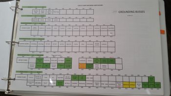
Thus, the first thing I did today was called Bob at TCW and left him a voicemail with an overview of my dilemma. I then worked on some needed updates on this web site for a couple hours. I also updated my grounding buss pinout matrix (below).
As I was finishing up some administrivia, Bob called me back. He essentially told me to roll up my sleeves, sharpen my #2 pencils and start taking some notes. Also, I needed to reach back into the recesses of my mind and not only find, but dust off, Ohm’s Law, because we were going to need it to figure these babies out boys & girls!
To make a long story short, the bottom line in getting to the holy grail figure of 20 milliamps or below when one is incorporating a relay with an airspeed switch is to ensure the relay coil resistance is above 600 ohms minimum, which of course drives down the amount of current (using 12V power = < 20 mA) that can pass through it. Ok, so I got that down, plus the need to use a protective parallel diode, much as we do on our main power battery contactors.
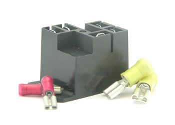
After getting off the phone with Bob I just needed to take a breath and do some self inventory, of my relays of course. Sadly, the quintessential B&C-sold S704-1 relay (below), of which I have a few at the ready, have a relay coil resistance of 144 ohms. No good! I then had to go on the hunt for the proper relays on Mouser to find acceptably rated relays.
Moreover, the sticky wicket for a high-current-powered item like the heating element in the pitot tube is that relays that have high coil resistance typically handle lower current loads. Nonetheless, I have an order queued up with mouser, and will test out a few different relays. I also have an alternate design to stick with my S704-1 relay as the first line relay to power the pitot tube, which itself would be controlled by a much smaller second line relay controlled by the airspeed switch (AS003). (relay photo from BandC.biz)
With all my new found knowledge on airspeed switches, I quickly got it all annotated on paper by then doing yet another major design overhaul on my Lights Wiring Diagram. After ensuring I have everything identified that I need up to this point, I’ll pull the trigger on my mouser order in the next day or two.
Ok, the taxi light operations and airspeed switch incorporation really were the last 2 long poles in the tent as far as electrical system design that I had serious questions on. With the code cracked on both of those, I can move on to finishing round #1 on the Triparagon & avionics bay/nose components wiring. I’m sure I’ll have wiring questions on some of the panel devices and the engine ignition & monitoring component wiring, but that’s a ways down the road. Thus, I feel confident that I should be done with all these electrical system shenanigans over the next week.
Tomorrow I plan on really focusing on finishing up the Triparagon install.