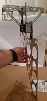
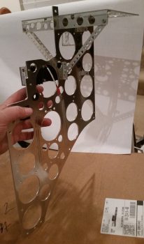
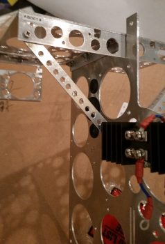
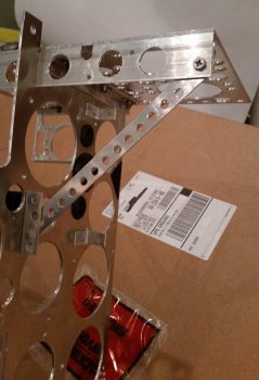
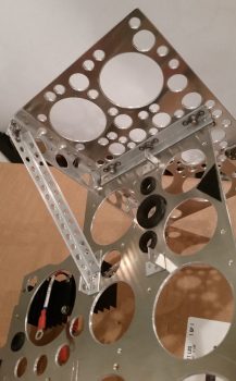
Funny, before I sent a few pics of my progress to my buddy Marco, I was thinking that this thing sure does look like an Erector Set. Sure enough, Marco texted back the same thing so I figured it would be a fitting title for today’s post.
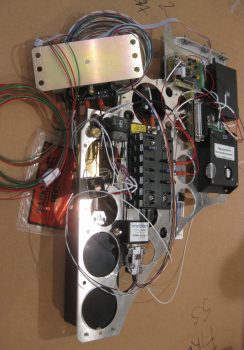
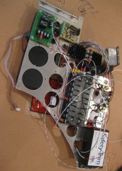
I started off with a couple of shots of the Triparagon showing how it looks as removed from the airplane with all the electrical accoutrements attached. You can see on the right side that there’s a big bare spot where the original X-Bus once resided. Now I have more space to mount more toys in the future!
The goal for the day was at a minimum to get the diagonal supports in for the cross shelf. I was able to accomplish that. I was also trying to get the last round of lightening holes drilled on the Triparagon vertical plate . . . that did not happen.
I got to work by stripping the Triparagon of all of its encumbering components, ensuring that each component and its hardware got bagged so as to keep track of they myriad of little pieces parts.
I then gathered up my 1/2″ x 1/2″ by 1/16″ thick 2024 angled aluminum extrusion and did a bunch of figuring out, measuring and head-scratching to configure the right side diagonal support. Because of the location and angle that it intersects with the vertical plate, I went ahead and decided to simply mount it with 2 x 4-40 screws to the aft end of the Schottky diode heat sink, which in turn is of course mounted to the Triparagon vertical plate.
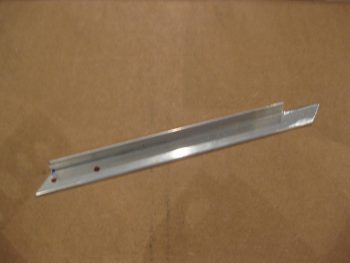
After getting all my measurements and angles finalized, I marked up the extrusion and cut it. Since it’s really cold outside and it was more trouble than it was worth to pull out a miter saw, I simply cut this by hand using my German hack saw. I needed to remove a length of one side of the angled extrusion on the top-oriented end to make room for the static line attached to airspeed switch #1. I cut the perpendicular side with my hacksaw, but for the rip cut at the corner edge I used the Dremel with a cutoff wheel (pic is a bit blurry).
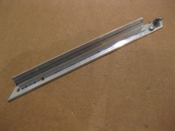
I then drilled a hole for a #8 screw through both the diagonal support and the right corner of the cross shelf overhang mounting tab. I then drilled and riveted a K1000-8 nutplate to the top end of the support arm. As you can see, I also marked the diagonal support arm with lines running the full length to drill lightening holes.
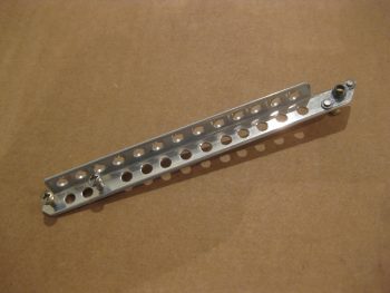
I then drilled a series of 3/16″ lightening holes. Although I used my drill press, they’re still far from perfect. But they lighten the piece and provide holes to secure wires to, so requirement met!
Here’s a shot of the finished right-side diagonal support arm for the Triparagon cross shelf.
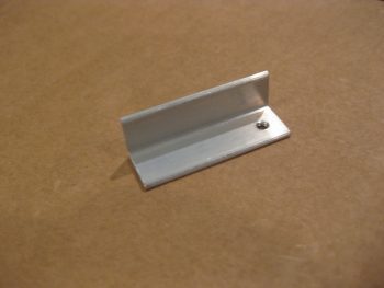
On the left side I had nothing to mount the support arm to on the lower end of the arm, so I cut a 1.55″ piece of 1/2″ x 1/2″ by 1/16″ thick 2024 angled aluminum extrusion to make a small mount bracket. I planned to have the mount secured to the vertical Triparagon plate using the same 2 screws that also secures the aft edge of the Schottky diode heat sink (different screws than the 4-40 ones used above to mount the right side support arm).
I set the length (technically height) of the mounting bracket so that the screw holes would be about 0.2″ in from the top & bottom edge, so after cutting the mounting bracket to 1.55″ I simply marked and drilled a hole 0.2″ from the edge. I also tapped the hole to accept a 4-40 screw. I can of course drill this out later if I simply want to use a nut with the screw later on.
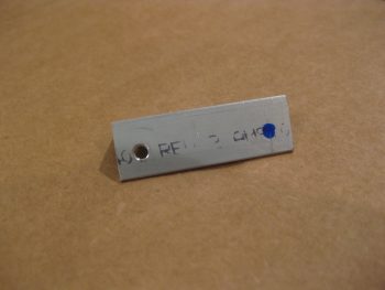
I then mounted the bracket in place, removed the lower screw and marked the hole with a Sharpie. I then removed the bracket and prepped it for drilling.
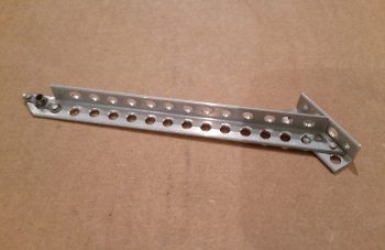
Jumping ahead (I had a pic or two in-between, but they came out frustratingly blurry!), here’s the completed left side diagonal support arm. Note that I used rivets to secure the arm to the mounting bracket. Also note that I drilled a number of lightening holes in not only the support arm, but the mounting bracket as well.
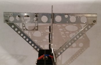
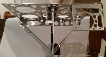
I then mounted the diagonal support arms in place on the Triparagon and snapped a bunch of pics.
Here’s a shot from the front right side of the Triparagon looking aft.
And another one from the front left side looking aft.
A head on shot looking aft.
And what you would see if the instrument panel was see-thru.
A bit closer from the front right & left looking aft.
A low angle shot looking from the left side forward.
And the final low angle shot looking from the right side forward.
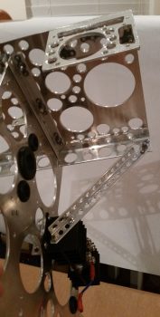
Tomorrow I’ll remove the cross shelf and the diagonal support arms and drill the final round of lightening holes into the vertical Triparagon plate, which will be the end of my Lightening hole drilling on this thing! Once done I’ll clean up the holes and then start back with the final (permanent) mounting of the electrical components on the Triparagon. Then over the next few days I’ll get as much of the cross-wiring and interconnects knocked out as I can. Once that’s done –as well as a few minor Adel clamp hard points, click bonds, etc. floxed & glassed into the avionics bay area– I’ll call it quits on the electrical stuff for a while AND… get back to work on the wheel pants!

