
Another post covering the last 2 days…
Yes, all the electrical system mods and change ‘chickens’ are coming home to roost, and working these changes into the matrix, above and beyond the standard effort to get all the electrical system installed correctly, is proving to be a big time drain.
A simple example is my trimming down the pair of nose gear indicators lights (“Gear UP transit” and “Gear DN transit”) to only one indicator light that depicts simply “Gear in transit.” Besides verifying the circuitry, this will require disassembling 3 different connector shells, soldering in and heat shrinking a pair of diodes, and repopulating empty connector slots with currently loose wires. Then tying the ground side of the new sole indicator light to the dimmer circuit. Plus relabeling all the wires involved. A 2 hour task for REMOVING A LIGHT… Crazy!
I started off today going through my electrical boxes to collect up all the washers for all the instrument panel B&C switches that use FastOn connectors, since those clearly don’t need to be soldered prior to install.
Here we have the left side and center of the panel, with the Fuel Pump switch under the red flip up cover and the 2 center landing light and nav/strobe switches. Now, I did install the RAM air scoop rocker switch just to the left of the Fuel Pump switch since it has a Molex connector pigtail for connection.
Also, note the bottom left corner panel eyeball vent and center strut RAM ball mount are both installed.
 On the right side of the panel we have the “Big 3” switches inside the switch guards: the Master Switch, Electrical Ignition #1 (Electroair), and Electrical Ignition #2 (P-Mag)… all currently un-wired. However, the P-Mag 3A circuit breaker near the sidewall is actually wired as is the bottom contact of the Auxiliary Alternator (SD-8) 2A circuit breaker. The other side of that CB will connect to switch 003 in the Warning Annunciator Sub-panel.
Finally, nestled in between the rows of the Big 3 switches and the circuit breakers is the diminutive TACH 1 ↔ TACH 2 switch, which I soldered-terminated its wires and installed.
 I will note that after some assessment, I moved the large wire bundle coming from the aft of the aircraft from the edge of the right leg hole to the sidewall, outboard of the elevator control tube. I actually created a padded plate out of scrap carbon fiber to secure the wire bundle and will install (flox) an Adel clamp threaded insert into the sidewall.
It was all looking fairly tidy until I discovered the bottom connector tab of the P-Mag CB was touching the control stick cable’s securing Adel clamp just above the screw holding it. Thus I had to mark the offending areas, disassemble everything in that immediate area to grind down both the Adel clamp edge and the circuit breaker bottom tab to allow for about 1/8″ clearance. Yep, the clearance is tight and minor tasks seemingly unending!
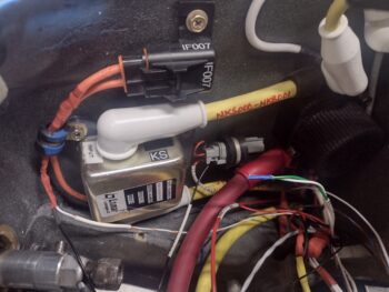
An unexpected break that I did get was when I started deconstructing the mess that was the clear heat shrink over the CS ammeter in the nose battery compartment. It had 2 layers of clear heat shrink, the final one being too large so that the ends were open and of course the 3 ugly yellow zip ties securing the original heat shrink that came with the CS ammeter, but didn’t quite fit.
Well, apparently by applying heat to the added clear heat shrink, the original cut heat shrink actually shrank to secure itself around the CS ammeter. Since it is cut to fit, I simply re-affixed the label back in place and then added 2 less conspicuous white zip ties and called it good.
The case of the UGLY CS ammeter has been solved… moving on!
 Elsewhere in the nose battery compartment… I nearly forgot to install the 2-wire control connector for the starter contactor. Another lucky break in that there was a threaded hardpoint that I had originally installed for the battery cable, but decided the angle/ configuration wasn’t correct so left the cable unsecured at that point. However, that open threaded insert allowed me to secure the control wire connector with an Adel clamp just aft of the starter contactor.
In addition, I replaced the starter contactor’s inline fuse Adel clamp with a slightly larger one and secured BOTH leads of the fuse vs just one. Much cleaner, and better positions the exiting wires.
 Finally, today I met Guy at Phil’s shop to pick up the left wing. After some final thinking —although I clearly have some work to do on the wing to get it ready for final install— I made the decision to take it to my hangar vs back to my home shop. Yes, the transition of working on the plane at the hangar vs my home shop has just begun.
Pressing forward!