
I was not looking forward to the first task of the day! But I knew it had to be done to move forward… another one of these right-of-passage tasks that are so common in a Long-EZ build. Only this one was self-inflicted.
Sigh.
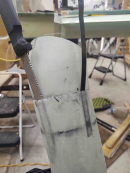
I started out by slowly getting a flat metal blade and a larger knife down into the space between the aft RAM air piece flange and the aft opening of the front RAM air piece. And although I didn’t want to do it, I needed a way to soften up that tape…. so whatever area I got the knife into, I poured a couple drops of Goo-B-Gone on each side of the blade, where the edge was pulled away just a hair.
That actually did the trick. It softened up the tape enough were I could then manipulate the knife until I eventually could get the knife all the way around the flange/scoop assembly… somewhat like an old style can opener.
However, that was just phase 1. When I tried every which way to cajole the aft piece out of the front section, it just wasn’t having it. I tried using strap wrenches to twist the two parts in opposite directions… no joy. I realized that most likely the only solution was pulling the flanged aft piece “straight” out of the front section.
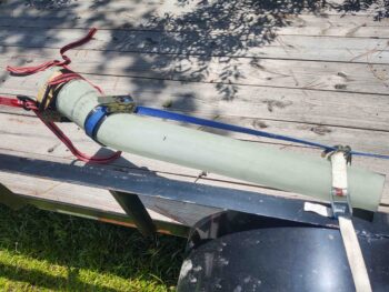
I wrapped up both sides with a decent amount of Gorilla duct tape to give my tie-down straps an edge to grip to. I added some cardboard under the tie-down straps so as not to damage the RAM air scoop pieces.
I then tied off the tie-down strap attached to the long end to the back of my trailer.
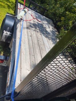
And attached yet another tie-down strap to the one securing the short aft RAM air piece. I ratcheted the front tie-down strap just a bit and then started applying heat from my heat gun all around the joint.
I could see the pieces started to slowly separate so I applied a bit more pulling power on the front tie-down strap while continuing what I thought was a spread out judicious use of heat. In just a couple of minutes the two parts of the RAM air scoop separated somewhat easily using this method.
I then quickly took the tie-down straps off because I didn’t want any possible lingering deformation from the heat I had applied to the flange joint.
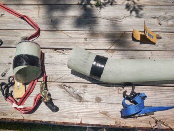
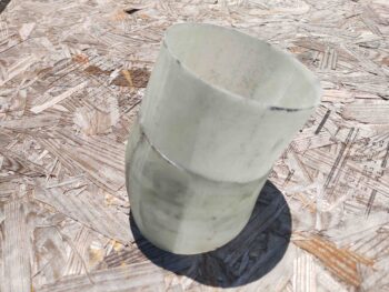
Here’s the 2.5″ flange off the aft RAM air piece after I cut it to length and cleaned it up.
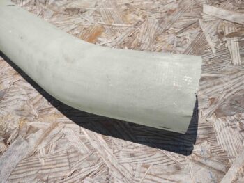
Here’s the long forward section of the RAM air scoop. Note that not only is there some minor physical damage at the aft edge where I had to jam the knife into the tape seam, but also some minor epoxy burnout caused by the heat gun. I’ll cover up –literally– both of these issues with a ply of BID around this aft area. The damage is definitely not something that requires any major repair(s).
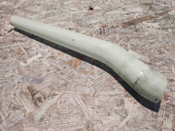
Here we have the front and aft sections of the RAM air scoop mated together.
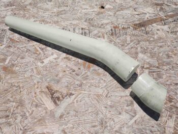
And a look from the aft end… not a bad fit if I do say so myself.

And the best part is that this time the two sections of the RAM air scoop come apart WAY easier than before!
After spending a decent amount of time washing the RAM air scoop sections with both Dawn dishwashing detergent and Simple Green to remove as much of the Goo-B-Gone as possible, I then got to work on mounting the RAM air can to the aft face of the firewall.
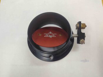
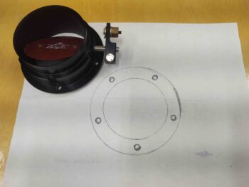
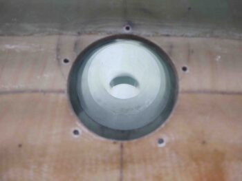
I started by dismantling the RAM air can and then placing the front nose piece on a piece of scrap paper.
I then traced out the inside and outside diameters of the mounting flange piece, as well as the screw holes.
I then used my paper template to locate and drill holes through the firewall to allow me to mount the RAM air can nose piece, and thus the entire unit, directly to the aft face of the firewall.
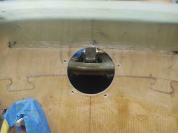
If the mounting holes look a little tilted or slanted to one side, it’s because they are due to the butterfly valve actuating rod not being parallel to the horizontal cross mounting holes. Clearly it was more important to get the actuator rod level since I want the open/close actuator action to happen both vertically, and perpendicular to the rod.
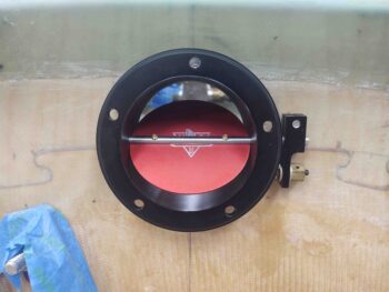
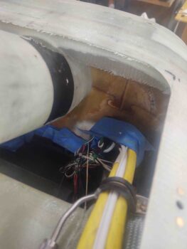
Here we have a shot from the aft firewall side looking through the RAM air scoop. Note that the bends are so shallow that you can actually see out the front of the RAM air scoop from the aft side, and vise versa.
My last tasks of the evening involved a couple layups, which while somewhat routine as far layups go, were pretty darn significant in my book.
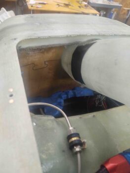
The first layup involved getting the tape-joined RAM air scoop aligned with the centerline of the aircraft, and then securing the very aft edge to the front face of the firewall —in the hell hole— with a flox fillet and 2 plies of BID.
This officially mounts the RAM air scoop into the hell hole, and allows me to then move forward in integrating the scoop into the hell hole hatch cover.
The second layup was the aft hell hole flange just above the RAM air scoop, and was also a 2-ply BID layup. Once it cures I can then proceed with installing the 2 aft corner nutplates to secure the hell hole hatch cover to the hell hole flanges. This layup finishes the construction of the hell hole flanges.
Tomorrow I’ll work to finish off the prerequisite steps required to mount the RAM air scoop into the hell hole hatch cover.