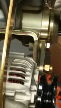
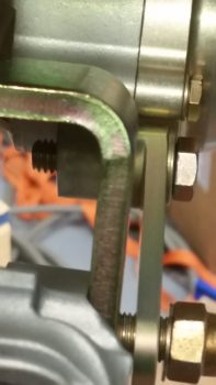
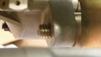
I started off today by going down to my local Village Hardware store to see if they had a #8 “aircraft grade” 1-1/4″ x 5/16-18 bolt on hand. This little hardware store rarely disappoints and they continued their tradition today. The 1″ bolt I had in place for mounting the alternator-to-starter support link was just a tad short and I wanted to keep with showing the requisite 2 threads on any given mounted bolt. As you can see, the 1-1/4″ bolt does the trick.
[If you’re wondering why I went with a #8 grade bolt here, try finding course threaded 5/16″ bolts on Aircraft Spruce, Wicks, etc. If you do, they are most likely very expensive and for a very specific purpose, such as my Lycoming starter mounting bolt].
As visible in the pics above, I already have one washer in place, and with either an added lock washer or a set of Nord-Locks there will still be visible threads.
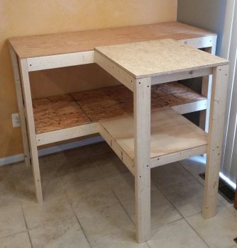
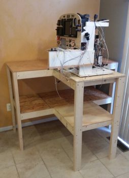
Yes, not overly exciting stuff to report on a workbench, but in the reality of my upcoming move to NC it is a necessity of sorts that demanded a bit of time to complete this workbench for electrical work, storage, and of course a place to work on my instrument panel mockup.
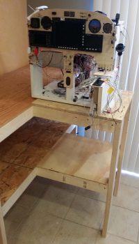
I finally got my instrument panel mockup off the floor and back onto something where I can both clearly see what I’m doing (without killing my back!) and have unobstructed access to 3 sides of the panel mockup.
Another shot of the instrument panel mockup’s new home.
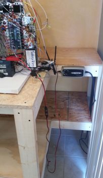
Although a minor detail, whenever I ventured to the aft side of the panel mockup to do work I often found myself inadvertently kicking or stepping on the battery charger that was lying on the floor. Well, no more! With a nice industrial wood bench I simply mounted the battery charger to the work bench frame. A minor feat, but definitely a nice improvement over what I had before.
I then took a break after my bench building endeavors and set about to adding a number of additional component serial numbers to my Excel spreadsheet tracking list.
Moving on . . .
As I was returning home from NC I stopped off to check my mail and noticed my driver’s side headlight was out. I had bought my other headlight at Advanced Auto Parts, and coincidentally, this auto parts chain just bought out CarQuest, the maker of the belts that B&C sells for their alternators. Armed with that knowledge, when I went to buy a new headlight I queried the folks at Advance Auto Parts about ordering a couple new shorter alternator belts (again, since I now have a 7.5″ diameter flywheel pulley). For some reason their system wouldn’t let me backorder the belts, so when I got home I tried online. No joy.
After spending another half hour looking for these darn alternator belts, I punted and decided to simply order them from B&C. In an effort to consolidate, be efficient and have no wasted motion on my B&C order, I decided to finalize my requirements for the engine grounding strap and order it concurrently with the shorter alternator belts (primary + spare) . . . but how long did the grounding strap need to be? And what size mounting bolt holes on each end?
I spent a few hours researching the best location for the engine ground. Yes, there is a nice factory provided threaded hole on the left side of the engine casing, but since my firewall ground post and starter are on the right side, I am attempting to keep the engine ground strap on the right half engine crankcase if possible. Finding a spot to mount the engine ground strap also required spending well over an hour digging into my baffling requirements, since I am attempting as best possible to stay clear of any baffle mounting holes. Again, since both the starter and the firewall grounding lug is on the right side, I also wanted my engine grounding point location to be on the right side engine case for the cleanest electrical path.
After assessing what other builders had done, getting a decent layout of how the baffles would get mounted, and having a general targeted area of where I wanted to mount the engine grounding strap, I then mocked up my engine mount onto the firewall (lying horizontally) to get a decent swag as to the required length of the engine ground strap.
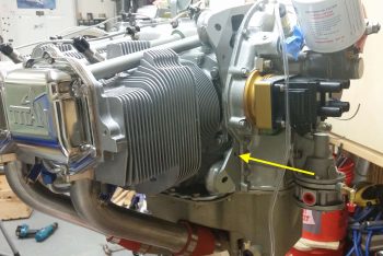
My original goal for the engine ground strap was to get it as close as possible to the starter, but besides mandating a much longer ground strap (weight), the best mounting positions for a ground strap are holes that will be used for attaching the baffles to the engine. I decided that if I have a good location on the forward right engine case (next to the accessory case but still right engine half) that the electrons will still easily be able to make their way through about 16″ of good steel. If not, I’ll readdress as required.
After scouring the right side of the engine for a good spot to mount the grounding strap, I finally decided on the location (yellow arrow above). I then extrapolated the required grounding strap length and double checked it with my engine mount on firewall mockup. The resulting strap length, with some room for maneuvering through the maze of hoses, etc. and generally slack for anti-vibration purposes came out to 13″, with a 5/16″ mounting hole on each end.
Thus, my final act of the evening was doing what I do best on this build: spend money! I pulled the trigger on two 7312 XL alternator belts (again, primary and spare) and 13″ engine grounding strap.
Currently, that completes the inventory for all the required major engine components, minus the fire sleeved hoses. I’m sure a few bits of hardware and fittings etc. will be required, but I’ve closed out all engine component requirements that I am currently aware of.

Wade, great to see the Beasley Baffles working out for you and thanks for the kudos! Your build is inspiring and I can’t wait to be sitting on the ramp with you at Rough River (but I won’t park beside you because you’ll make my plane look like crap! Lol!).
Mike, of course! And thanks for the ton of assistance over the years. Your site and advice over the years has definitely made my build much, much easier. Haha! Well, the key part of your statement being our birds sitting on the ramp at RR!! ;)