
Today was all about cleanup actions to finish up what I’ve been working on over the last few days and a myriad of other seemingly small tasks.
I started off with identifying the location of the landing brake relay pack hardpoint just aft & low of the P4 Throttle handle cable connector bracket on the left side of the avionics bay, just forward of the left arm rest. I then found a RivNut lying around and scarfed it up to press into service to hold the 2 back-to-back metal cable clamps that had once resided on the forward side of the NG30 cover to hold in place Jack W’s EZNoseLift system relay pack. Since my relays for the new nose gear are nice & tucked away in the RCU, it allowed me to reutilize these clamps to secure the inline relays that Jack W. uses on his landing brake system.
I Dremeled some grooves into the RivNut side for gripping, screwed on a taped-up washer for mounting, taped up the open end with duct tape, and then hit it with some Acetone to clean it up.
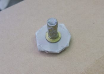
I then drilled out the hole and prepped it for inserting the RivNut hardpoint.
I used some fast hardener with the MGS 335 that I still have on hand and floxed ‘er in. I then clamped a 1×2 stick to the panel to keep the RivNut firmly in place.
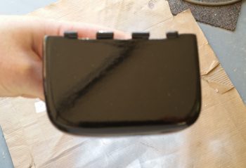
While the flox for the landing brake relay RivNut hardpoint cured, I then lightly sanded the problem child from hell (AKA “the tool box lid”) and hit it with 3 coats of gloss black paint. True to form, it was a slightly breezy day outside and the paint had lots of nice little added surface bits by the time I was done. I had already decided to actually wet sand these and finish them with clear coat and then buff them out. That’s the major reason I haven’t riveted the latch on the lower tool box. I wasn’t really planning on going in that direction, but for some inexplicable reason this particular paint has been such a challenge that I don’t see any other way right now… that is if I want decent looking paint on the tool box. And I do.
Another issue, that I discussed with Marco while he was here, is the fine splitting that is going on with the 3D-printed AEM box. Since Acetone melts –and thus “glues”– 3D printed material together, I clamped up the AEM box on the corners to close up the fine gaps & splits going on, particularly at the corners. I then wiped down the surface with Acetone. I waited about 6 hours and did it again, then left the clamps in place overnight to let it really set in.
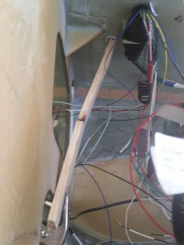
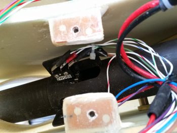
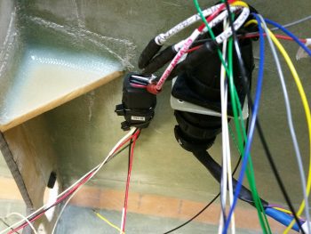
I always believe things happen for a reason, and one really good thing to come out of my intermittent brown wire goose chase on the new nose gear wiring was that I found a loose terminal on the micro lever switch (sw088) that is 1 of 2 micro lever switches that drives the gear/canopy warning module. I reterminated that switch (the red FASTON visible in the middle of the pack) and re-secured the wires on that gear actuator motor flange with a zip tie.
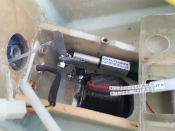
I then spent a couple of hours working on the taxi light actuator linkage geometry. I really dialed it in much closer, but still have some stuff to figure out on it. The actuator does a good job moving the taxi light assembly down in place and then back up close to seating back into the hole. With the linkage between the actuator lever and taxi light being variable, it currently doesn’t have enough pull to keep the light up in its bay that last 3/16″. I’m much closer to a solution, so I’ll let this germinate another day or two while I tackle other nose-related stuff.
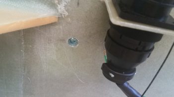
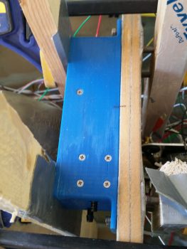
Back to the landing brake relay RivNut hardpoint: here are the mounted clamps after I pulled off the taped-up washer and cleaned up the flox remnants from around the RivNut opening.
I then used 2 zip ties to secure the inline landing brake relay pack in place. After about 30 minutes, I then cut these zip ties to allow me to remove the P4 connector to take it upstairs and finish terminating 5 wires (4 to the roll trim relay board with #5 being roll trim reporting to the GRT HXr EFIS … all on the Triparagon). With these 5 wires terminated, my P4 connector is really officially finished!
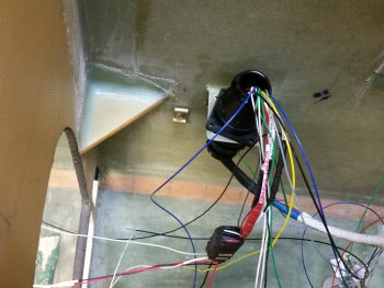
I then spent a good 20 minutes assessing the fit & mounting location of my GNS480 mounting bracket, or “tube” as Garmin calls it. I placed the tube in position against the back of the instrument panel, allowing clearance for the sidewall, then traced around the front edge of the tube onto the back panel surface. I then made some measurements & annotated those for later use to determine final mounting positions for panel components (Trio autopilot, EFIS, clock, etc.)
With my shop tasks done for the evening, I then removed the Triparagon from the plane and took it upstairs. You see, when Marco was here I thought I may have inadvertently fried one of my AG6 warning annunciator units. So, I spent a few minutes hooking them up to test them out, and thankfully both tested out fine (Lesson REITERATED: Always use a fuse… I’m fairly certain its selfless sacrifice saved my AG6!)
I then spent a couple of hours really making the final touches on 6 of my wiring diagrams. As I’m knocking out the physical wiring on these connectors, it really allows me to fine tune the wiring diagrams with wire gauges, wire colors, physical wire routing, connector pin numbers, wire labels, and component IDs (e.g. I just recently finalized my LED indicator light ID’s). I printed all the newly updated wiring diagrams out and then sent the files to myself via email as a quick backup for each diagram.