
First off, I want to apologize for the first two pics being out of focus. It’s hard to tell sometimes how they look on the phone screen until later on. I think there’s plenty enough detail to get the idea of what I’m on about with these pics though.
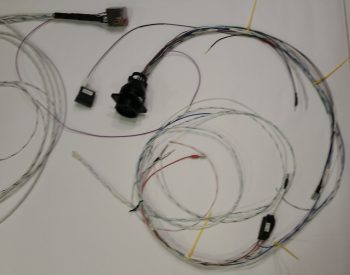
I started off today wiring up the remaining cavities in the P5 connector, which routes all the wires for the pilot Infinity control stick grip. The proof is in the pudding when completing these bigger wiring tasks, as so too it is when you finally get down to wiring up these connectors to the end components. I spent a fair amount of time working over the pinout diagrams beforehand to make sure they were as spot-on as possible, but when the wiring starts –like any best laid plans– things change. Wiring sizes, wiring colors, wire size or color availability on-hand, routing, etc.
In addition, since my new nose gear system is operational, I’ve been scavenging the longer, terminated wires off of the old nose gear wiring harness to use in both the P5 (and P4) connectors. This changes the wire colors sometimes since re-utilizing good terminated wires that may have a different random color than the first random color I chose is more important to me than sticking to an arbitrary random color! To be fair, some colors (power & ground) are a bit more sacrosanct to me, but the other random stuff I swap out in a heartbeat.
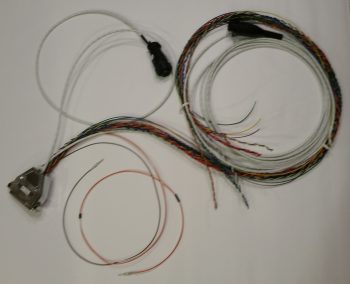
As you can imagine, there are a lot of rabbit holes to chase down to get all the wiring accounted for in these harnesses. With the P5 (control stick) and P4 (throttle) connectors being two behemoths in this wiring system, they really do interface with a lot of system end components. For example, although not a jaw-dropping number, if you look at the wires (there’s 3) in the lower left corner of the pic below of the associated Trio Pro Pilot Autopilot wiring harness, one goes to the P4 connector and the other two are terminated together into the P5 connector. To terminate these wires, a general idea of the routing and a quick mockup is in order to figure out the length. Obviously the length doesn’t have to be perfect, but longer is always better (EZ’er) than shorter.
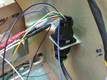
After figuring out, verifying, and finalizing all the wiring connections, terminations & routing on the P5 connector, I then set my sights on the P4 connector. It too deals with a myriad of electrical system end components in and around the panel, including Triparagon-mounted items, GNS480 GPS, and even the Landing Brake (see below). It took me a bit of time to verify the connections on these wires as well, but I confirmed all that was good, and tweaked a few things that had been superseded yet not annotated (by me!).
All in all it was a good day, and I’m really glad to have knocked these two connectors off of the list of prerequisite items that need to get completed before I start on the nose top. To be certain, in each connector there are a few wires that I actually didn’t mount into the actual connector cavities. However, I did cut all those wires to length and terminated them, so they are ready to go. This might help explain why you don’t see the wires wrapped with flightline tape nor any of the cable clamps mounted.
One thing that finalizing the P4 connector wiring above allowed me to do with minimal extra effort was to test out the operations of the Landing Brake using the throttle-mounted landing brake switch. I haven’t actually run the landing brake in (I think) going on almost 5 years now! So, to knock some of that rust off . . . here goes:
I do have about a half dozen connectors to terminate on the end unit side (mostly on the roll trim relay board), which I plan on getting to later tonight or earlier tomorrow. I’ll also be mounting some Adel clamps and wire-securing hardpoints in the avionics bay (area between the panel and F22) tomorrow as well.