Today was an amazingly busy day for the Long-EZ project.
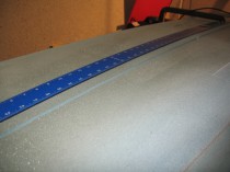
I made the initial cuts on the seat belt aluminum angle extrusion, and also planned and marked the bolt hole positions for the seatbelt/bracket attachments.
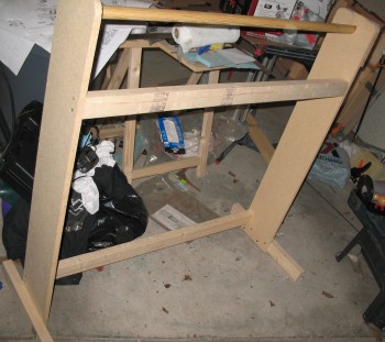
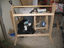
I dismantled the Fuselage Bottom’s sled and reclaimed the three 2x3s for the UNI glass stand that I designed last night. Then I went to the woodshop on Ramstein to cut the wood for the UNI glass stand. Being an avid wanna-be consolidator, or maybe opportunist, I also cut 4 each 1″x1″x3″ Spruce blocks for the CS spar imbedded hard points (these will come into play A LONG TIME from now!). I then cut some 1/4″ plywood into 2.4″ and 2.5″ strips for some future templates.
After yet another BAD experience of dealing with the ‘Know-it-all Nazis’ at the base wood shop, I decided I’d had enough. Besides being a pilot, my Dad was both a contractor and a cabinet maker, so I grew up on just about every wood-working tool known to man. And these wood shop guys on Ramstein treat every person in their presence as if it’s the first time they’ve ever seen a power tool. Thus, although I have crates of power tools, saws, etc. in storage somewhere in Virginia, I marched my happy butt over to the Base Exchange and bought a small 7-1/4″ chop saw to lessen my interface with those knucklefutzes, and thus lower my build time, decrease my angst, and maintain my sanity!
I went to the German version of, oh, we’ll call it True Value Hardware, Toom, and bought some Dremel bits and then returned home.
Ok, back to work!
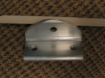
I drilled all the holes in the seat belt aluminum angle extrusions, and then cut one bracket completely out and filed down the edges. Although not a perfect specimen of machining, it looked pretty good! (Pardon the pic, I know it’s quite blurry)
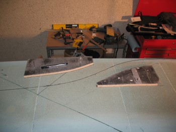
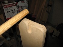
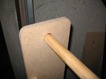
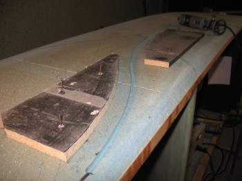
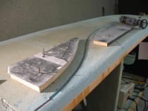
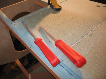
I then went from metal “machining” mode into woodworking mode and cut out the Dremel Tool templates—for routing the rudder cable Nylaflow conduit channel ‘S’ curve—out of the scrap particle board.
Since I had all my woodworking stuff out, I decided to knock out the UNI glass stand. I cut out a few more pieces (I did all the ‘heavy-lifting’ cutting at the base wood shop) and then finished building the UNI glass stand.
I took a break and talked to my buddy Marco to confirm some ideas and measurements (Steve Volovsek’s strake elbow-room mod, F22 center post width, Landing Brake LB22 & LB 23 dimensions, etc.). After our 1-hour long “strategy” session, it was time to get back to work.
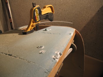
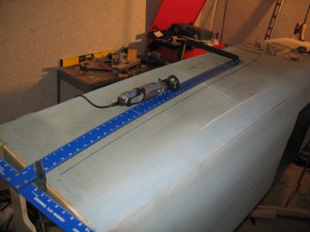
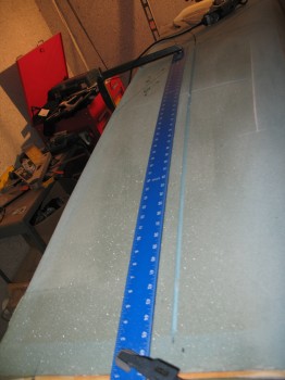
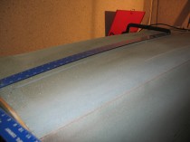
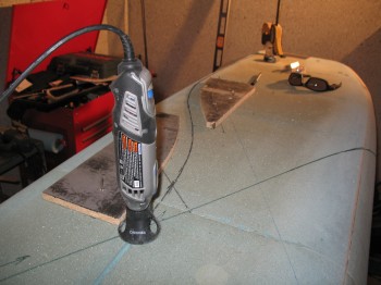
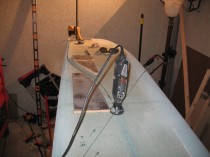
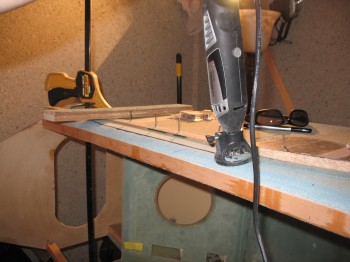
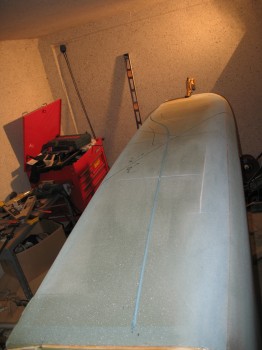
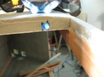
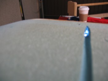
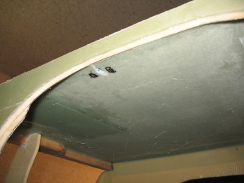
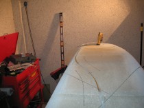
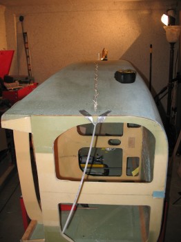
I set templates and then set up the Dremel tool. After double, triple, and quadruple checking everything, I pulled the trigger (literally! ha!) and Dremelled the channel along the Left side of the fuselage for the rudder cable conduit (Nylaflow).
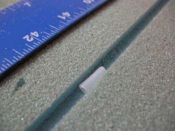
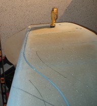
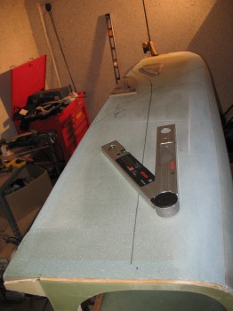
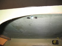
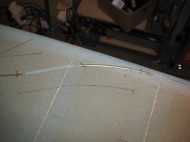
I also carefully drilled the holes at each end of the fuselage: AFT END – For the conduit to continue through the CS Spar and curve towards the outboard winglets . . .
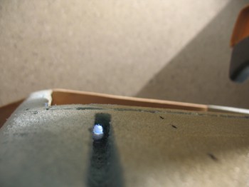
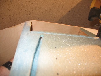
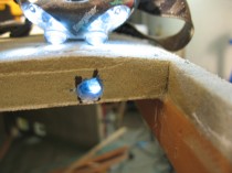
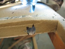
FWD END – To continue into the forward fuselage near to where the rudder/brake pedals will be positioned.
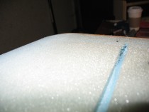
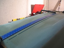
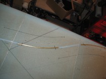
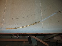
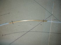
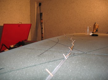
Although Nylaflow is some tough stuff, with a little bit sharper bends at the ‘S’ curves compared to anywhere else in the rudder cable conduit system, I decided I would reinforce it with some metal. I didn’t have any aluminum tubing, so the next best thing I could find locally was brass (at least that’s what it translated to!). I cut the brass tubing into two 9-7/8″ lengths for each side of the fuselage. I then chamfered the openings at each end. I cut 4″ of each end off of the 30″ long spring used for the trim system and set those pieces aside. I then used the remaining middle 22″ for shaping the brass tubing. It worked like a champ and didn’t deform the tubing at all.
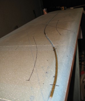
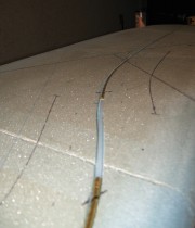
Once the brass tubing was bent and in place around the Nylaflow conduit, I micro’d the entire run of Nyloflow and brass tubing and held it into place with toothpicks.
Also, since I had the micro out, and still trying my hand at that efficiency stuff, I micro’d some foam chips into the main gear extrusion bolt holes in the foam.