
I started off today by cutting out the foam form for the RAM air scoop aft section. I then pulled the peel ply, trimmed the front and aft edges and cleaned up the piece.
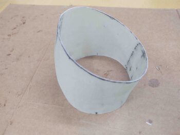
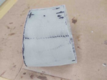
Here’s a side shot.
My goal in the following layup was to create a 2.5″ flange coming forward off the aft RAM air scoop piece that the front scoop section can slide on/off when being mounted or removed.
After taping up –for glass mold release– the inside lip on the aft end of the long RAM air scoop piece, I then mated the just-glassed aft section to the aft end fo the longer front end of the RAM air scoop and secured it with Gorilla duct tape.
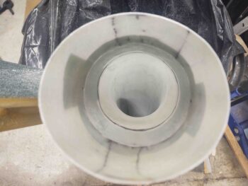
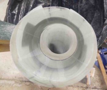
Here’s an inside shot. Not perfectly aligned between forward and aft sections, but definitely very close enough for what I’m doing here.
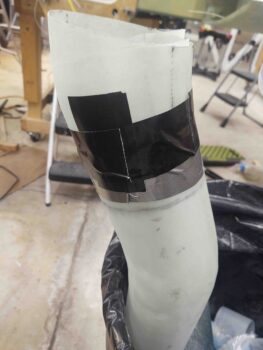
And a shot from the outside.
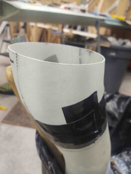
I then laid up 3 plies of BID that overlapped 2″ onto the aft scoop piece for permanent attachment and 2.5″ into the aft end of the forward scoop, over the packing tape. To keep it as smooth as possible for the air flowing through the scoop, I didn’t overlap the ends of the BID. I laid in 1 ply first then offset the joint of the prepregged 2-plies of BID by about 180°. I then peel plied the layup.
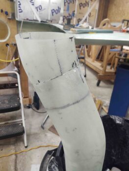
Here’s another exterior shot with the 3-ply BID flange layup complete. Note the shallow ‘S’ curve of the entire RAM air scoop.
Later in the evening the flange layup was cured… and, uh, well, I maybe mighta ought have thought this through a bit better! Ha!
After some feeble attempts to extract the aft piece from the forward air scoop I realized it was going to be quite an effort, and after about 20 minutes I kicked that can down the road until tomorrow.
The layup looks great and the peel ply is pulled… I just need to tackle the extraction and then I can press forward!