
I’ll start off with a task I knocked out last night, but forget to put it in yesterday’s blog. I’m adding it here for better continuity of this task subject.
After roughing up the micro with sandpaper in the nose landing light pocket, I used a small brush and some primer sprayed in a paper cup to primer up the micro with a couple of coats. I then left the primer to cure overnight.
Today I started off doing pretty much the same thing, just with a couple of coats of flat black paint. Here’s my nose landing light pocket bare foam micro fill patch after primer and paint. Not bad and this task is complete.
My next task on the nose landing light will be to cut and drill a 1/16″ thick lens to replace the much too thick 1/8″ thick lens.
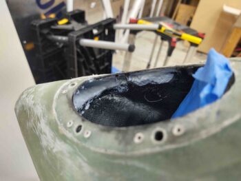
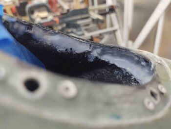
I used slow hardener on the hell hole left internal flange layup to allow me to knife edge it the very first thing this morning. My hypothesis paid off and it was just barely pliable enough for me to use a razor knife to trim off the overhanging 3 plies of BID.
A few hours later it was cured enough to allow me to re-drill the four 1/8″ pilot holes for the clecos, and then drill out the #2 spot and mount a CAMLOC (AKA Skybolt) receptacle and then mount a K1000-3 nutplate in the #3 position.
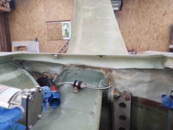
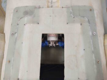
This gives me 2 installed CAMLOCs out the 4 total that will be used on this hell hole hatch cover/RAM air scoop mount. In addition, the 2 installed screws are out of the planned total of 9 on this entire assembly.
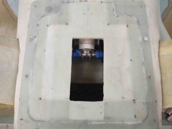
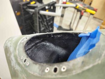
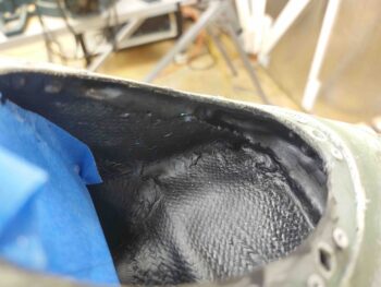
I was planning on moving right into assessing/configuring/shaping/glassing of the aft RAM air scoop piece, but decided what the heck, let’s take just another 20 minutes more and mount the K1000-3 nutplates at each of the front corners of the hell hole hatch cover.
Since I can’t get the solid rivet squeezer back into those corners because of the depth of the flanges and the “underside” (as situated) wall “overhangs,” I had to go with pop rivets to secure these corner nutplates. Moreover, because of the corner configurations, I went with a straight K1000-3 on the right front corner (left in pic) and a 90° nutplate on the left side (right in pic).
I’ll point out that I couldn’t proceed with the aft corner nutplate installs since I don’t have the hell hole internal aft edge flange glassed yet, which will have glass overlapping onto the side flanges in the aft corners.
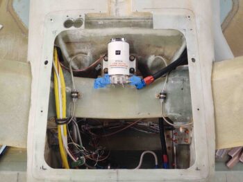
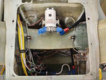
I then spent about 1.5 hours working the alignment, angles and overall configuration of the RAM air scoop aft piece that will be permanently mounted on the front face of the firewall in the hell hole. Once finished, there will be a flange on this small mounted piece of the RAM air scoop that the longer front portion of the air scoop will slide onto for a tight interference fit.
I’ll note that I would like the flange to be on the aft side of longer side of the RAM air scoop for both more clear work space when the hell hole hatch cover is removed and less surface disturbances of the air than with the flange edge facing forward…. but remember, the air scoop continues to gradually expand as it goes aft, so it would be physically impossible to go the opposite direction with the intersection flange.
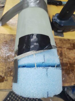
As it was —and as it continually is in building an airplane— I had to compromise with the shape of this last piece of the RAM air scoop puzzle. I had wanted the air to be presented to and enter the RAM air can entry nozzle at an exactly straight 0°. But alas, to get both top and bottom curves situated for a smooth transition, I had to cheat an estimated 5° on the angle. Again, hard to get perfect, optimized specs in a constrained environment with competing resources (i.e “space’).
Thus, in the pic above you can see I gapped the last piece of foam on both sides —the forward gap with the forward-positioned foam piece, the aft gap would be with the firewall face in the hell hole, about 1/4” on the bottom (as situated, technically the top).
After aligning left/right, up/down, forward/aft and securing the position with nails and toothpicks, I then filled the gap with pour foam.
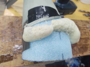
I then cut and sanded the cured pour foam to a pleasing (curved) shape! ha.
And as I did on the forward section of the RAM air scoop, I added pour foam to the inside curve part of this piece as well.
And shaped it into a nice (IMO) curve.
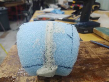
I then added the very original aft piece, which had the same diameter as the aft end of this plug to allow me to smoothly glass that 1/4″ extension to cover the gap between foam and firewall face. I then taped up the plug/form for glassing and marked the edge lines.
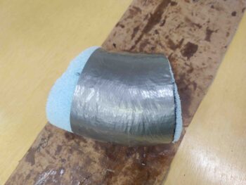
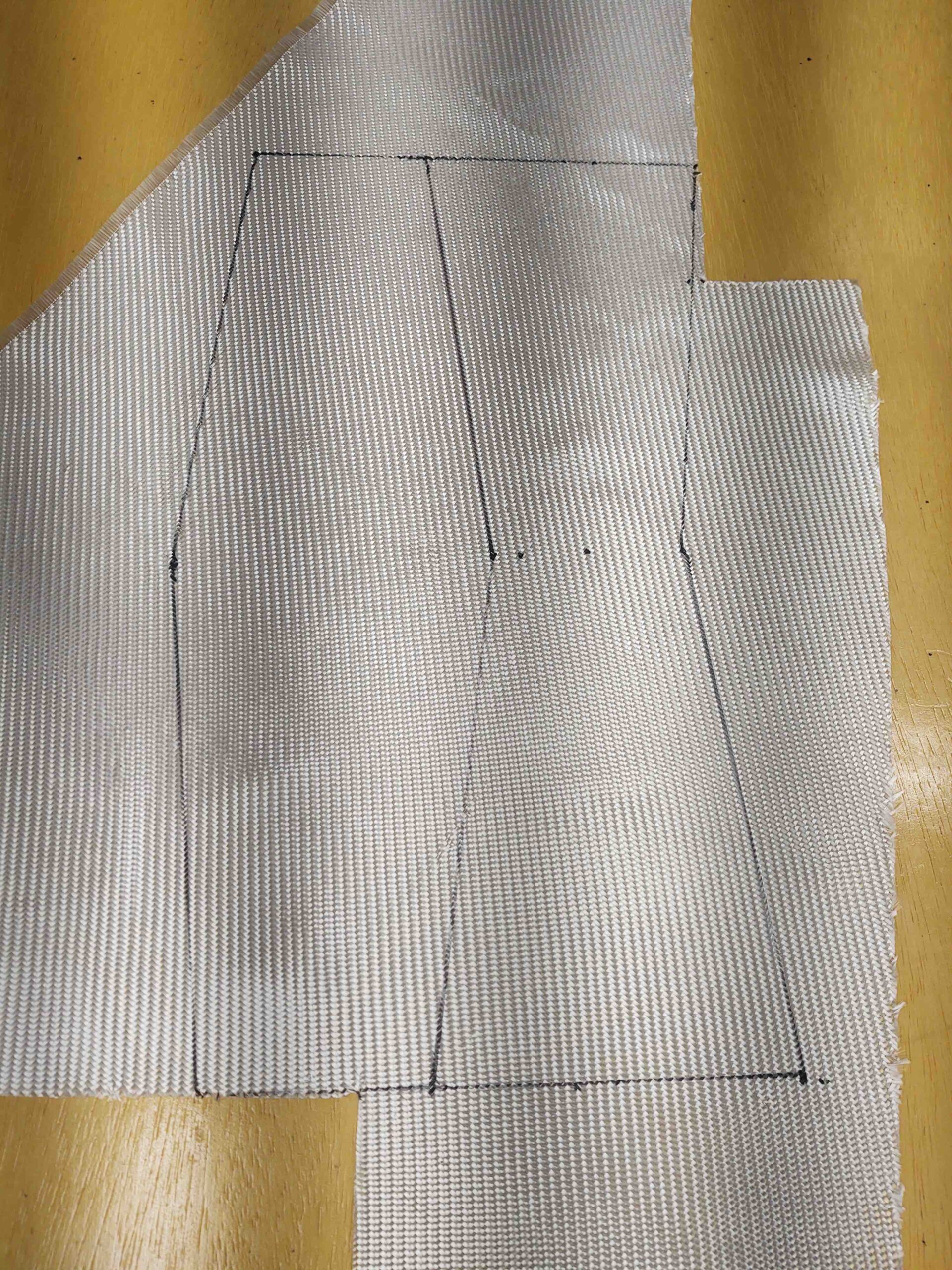
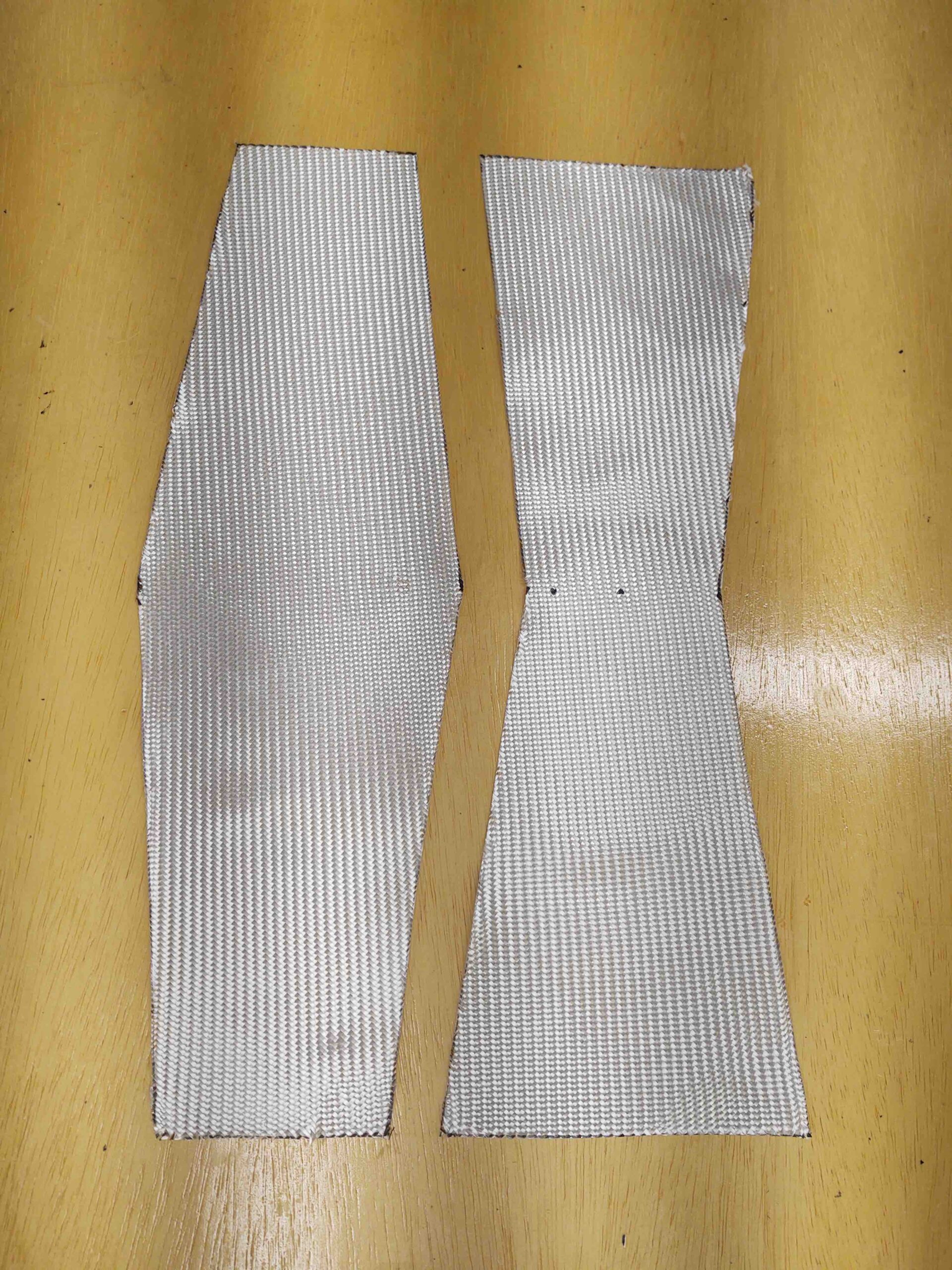
After measuring the short side curve and long side curve, and the circumference, I then cut my BID to overlap on opposite sides of this RAM air scoop aft piece. To be clear, these BID plies are ply #1 and ply #3 of this layup, with the middle ply being scrap UNI, just as I did on the longer RAM air scoop section.
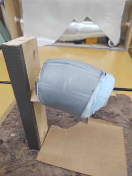
I then used a long drill bit holder/extension as a single-sided rotating spit to glass this RAM air scoop aft piece.
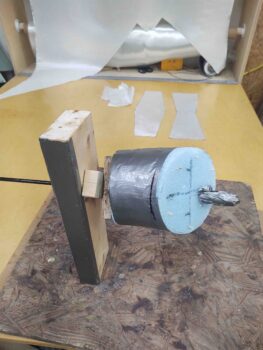
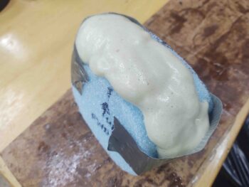
I started by applying peel ply to the entire surface of the plug/form duct tape. The peel ply helps even out and minimizes any irregularities in the surface of the tape, and of course results in a nicer smoother internal surface of the RAM air scoop aft piece.
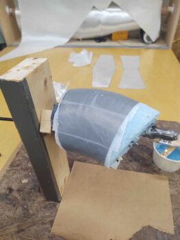
I then laid up the 3 plies of glass: BID-UNI-BID. I have to say my measurements were pretty spot-on and gave me almost exactly an inch overlap on both sides.
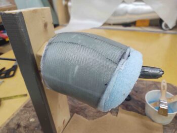
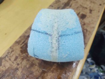
I then peel plied the external surface of this short RAM air scoop aft piece. I have to say for as small as this thing is, the glassing of it took about 3 hours start to finish, including glass procurement and cutting.
And as par usual, I then left this layup to cure overnight.