
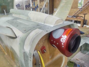
Today I started out by spending well over 30 minutes pulling the peel ply and cleaning up the layup on the RAM air scoop aft structure.
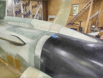
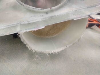
I then razor knifed the seam between the center segment of the RAM air scoop aft structure, what I’m calling the “firewall bridge” and the front edge of the bottom cowling. The cut wasn’t perfect and I’ll have to clean it up a tad during the finishing stage.
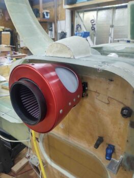
I then removed all the CAMLOCs from the bottom cowling and separated it from the fuselage/RAM air scoop aft structure.
And voila! Section #1 separated.
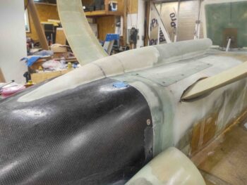
I then did the same thing at the forward side of the RAM air scoop aft structure firewall bridge by razor cutting the seam.
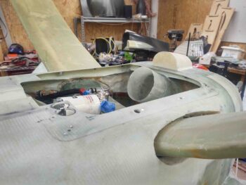
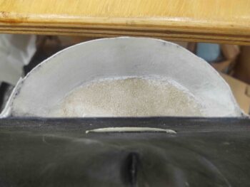
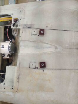
I then unscrewed and removed the RAM air scoop/hell hole hatch cover from the fuselage. As you can see I was left with just the permanently attached RAM air scoop aft structure firewall bridge.
A shot of the firewall bridge from the front looking aft.
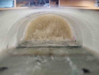
I then started cleaning out all the cured pour foam from inside the firewall bridge.
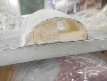
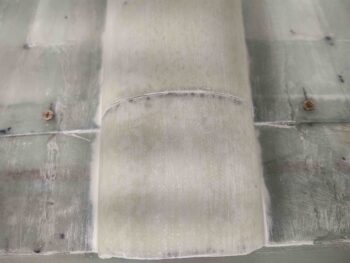
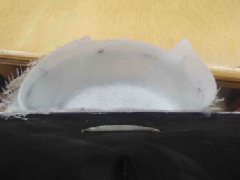
I didn’t use any micro on the foam around the firewall bridge, but did lay in some peel ply, which I pulled to have a nice clean surface for glassing.
I cut and prepregged 2 plies of BID and laid it up on the inside of the RAM air scoop aft structure firewall bridge, for a total of 4 plies of BID. Before laying up the glass I created flox fillets in the corners to ensure as much strength and rigidity as possible in the firewall bridge structure. I then peel plied the layup.
After removing the first 2″ of foam from the aft side of the RAM air scoop/hell hole hatch cover portion of the RAM air scoop aft structure, I then took it outside and cleaned up the glass with a Dremel tool sanding drum and some sandpaper.
I then laid up 2 plies of BID inside of that aft area. Since a screw will secure this portion of the RAM air scoop/hell hole hatch cover at bottom center to an upcoming flange on the forward side of the firewall bridge, I added a small 2″-wide ply of BID in the center of the layup (for 5 plies of BID total on the bottom center).
I then peel plied the layup.
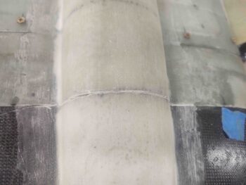
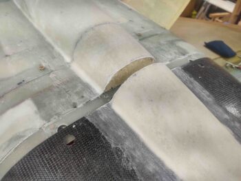
I then got to work doing pretty much the same thing on the very aft side of the RAM air scoop aft structure: the bottom cowling. I cleaned out the foam and sanded/prepped the cured glass for fresh glass.
Since nothing else will be glassed or embedded here, I went ahead and glassed the aft foam wall to create a pocket with the bottom (curved) side with 2 plies of BID (added here, so 4 plies total). I then peel plied the layup.
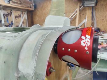
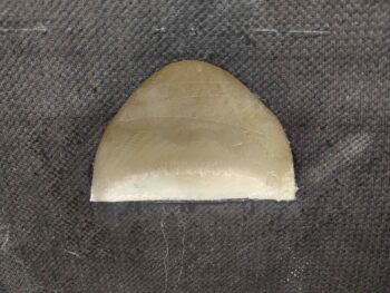
I’ll note on the 2 pics above that from the camera angle you can see a sliver of the RAM air can notch I made in the bottom cowling. Just for FYI, here’s the glassed, then foamed, RAM air can notch in the bottom cowling.
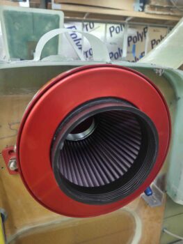
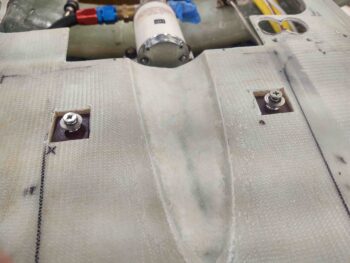
I then got to work on the last set of CAMLOCs that I’ll use to secure the RAM air scoop/hell hole hatch cover to the belly of the plane. These are the 1/4-phenolic block-mounted threaded Skybolt CAMLOC receptacles that have proven phenomenal on this build.
I had previously drilled 0.150″ diameter holes (one each side) through the RAM air scoop mounting flange into the bottom fuselage skin (just enough to penetrate the skin) to mark the positions of the CAMLOCs on both the flange and the aircraft belly.
I now centered the phenolic CAMLOC blocks on these holes and marked the perimeter of the respective blocks.
I then used the Fein saw to cut the outer skin, cleaned and vacuumed out the foam and debris, and then test fitted the phenolic CAMLOC blocks . . .
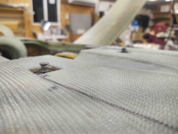
At which point I realized I had a big issue to contend with . . . you see, the bottom of these holes weren’t deep enough for the CAMLOCs to compress as they should in securing the RAM air scoop flange.
In fact, the CAMLOC in the left foreground of the pic below is a -2 stud, the shortest available and it is still too long, sitting too high to work.
Clearly I needed to ponder my predicament and make both a decision and plan for a way forward. I decided to sleep on it and work the problem tomorrow.
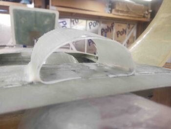
I moved on to my last task of the evening. Laying up a 3 ply flange on the forward side, and attached to, the internal surface of the firewall bridge. I taped up the inside of the aft edge of the RAM air scoop (all the previous layups were cured, BTW) as a mold release before laying up the 3-ply flange inside the firewall bridge, overlapping into/onto the forward RAM air scoop structure.
Moreover, to add more material to secure a K1000-3 nutplate, I added a 2″ wide 2-ply pad of BID to the bottom center (remember, inverted here, so top in this pic) of the layup. I then peel plied the layup and let it cure.
Tomorrow I’ll continue to work the interfaces of the RAM air scoop aft structure and getting those darn CAMLOC blocks installed.