
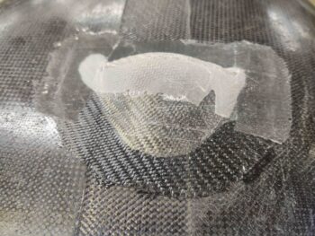
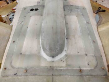
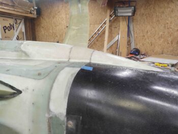
I started out today by pulling the peel ply and inspecting the 1-ply BID layup on the bottom surface of the lower cowling that will mainly serve to keep pour foam out of this clearance hole.
Moreover, I would say all is good but the glass at the corners lifted and separated from the cowling surface a bit. This will be along the edge of the RAM air scoop aft structure, or swoosh, or “canoe” if you will and will need to be trimmed down.
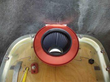
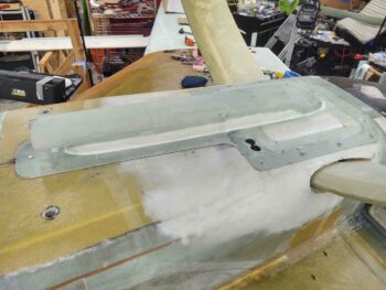
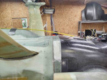
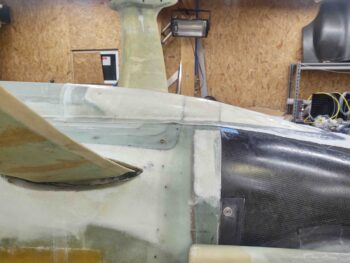
I then test fitted the bottom cowling to check clearance between the RAM air can and this new glassed pocket.

A shot from inside the cowling.
I then placed my shop LED light in the hell hole facing out and remounted the RAM air scoop/hell hole hatch cover securely in place. With the light shining though the LIDAR laser altimeter lenses’ holes I traced those holes on the surface of the hell hole hatch cover [Note the mounting base/flange to the RAM air scoop has been trimmed, see pics below].
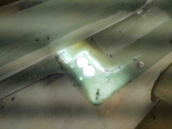
I then drilled the holes with a hole saw bit and sanded them out to size in the hell hole hatch cover to allow the LIDAR laser altimeter lenses to see the world. Note that prior to this I trimmed away the excess glass on the RAM air scoop mounting base/flange.
Another shot of all this from the side.
I then got to work on making up the 1/4″ thick phenolic inserts for the Skybolt threaded CAMLOC receptacles. These CAMLOC receptacles will be the second set to secure the RAM air scoop base/hell hole hatch cover to the airplane belly.
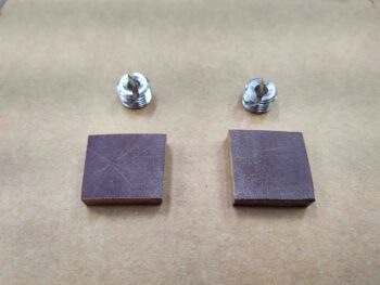
I drilled holes and tapped 1/2-20 threads in the holes for the Skybolt threaded CAMLOC receptacles.
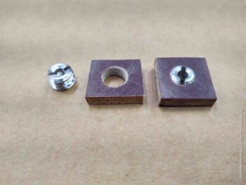
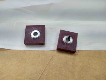
And then floxed the Skybolt threaded CAMLOC receptacles into the 1/4 thick phenolic inserts.
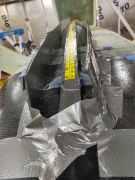
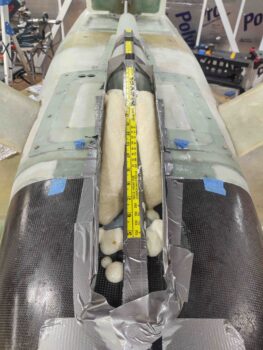
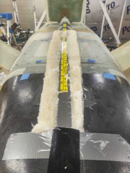
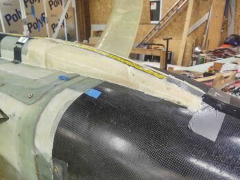
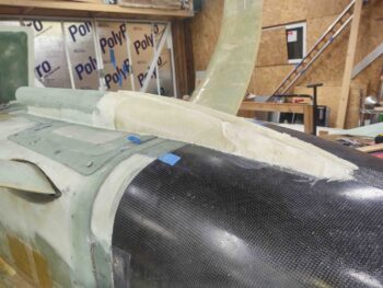
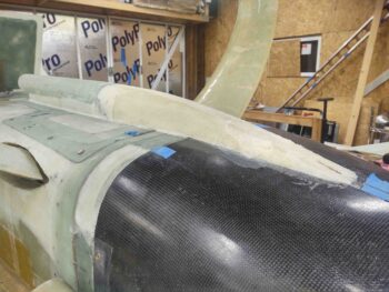
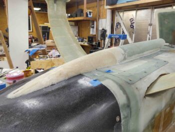
I then spent a bit finalizing my configuration for the RAM air scoop aft section structure. Using a taped-in-place flexible yardstick here is what the side profile will look like.
Before pouring foam though, I wanted to secure the aft inboard edge of the hell hole hatch cover as best possible. Since the width and shape of the RAM air scoop is now known, I could proceed with installing the aft inboard K1000-3 nutplates.
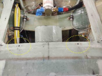
Here’s the hell hole hatch cover back in place, with all the CAMLOCs and screws installed, including the 2 new aft screws.
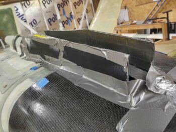
I then constructed my pour foam dam/form out of taped cardboard.
An angled shot of the taped-cardboard pour foam dam/form for the RAM air scoop aft section structure.
I then whipped up a batch of foam and poured it in the form.
Clearly it wasn’t enough foam.
So I waited my 10 minutes as per the directions and whipped up another batch and poured it in.
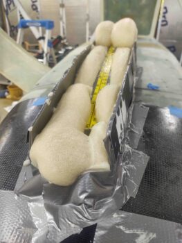
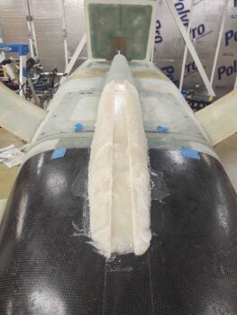
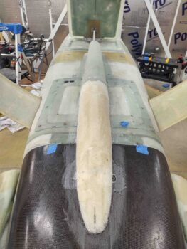
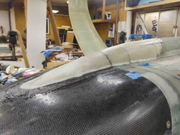
Much better this time, providing cover to all the areas. So I pulled the forms and started the slow process of trimming down the foam.
Here’s round 1 of some honest foam shaping.
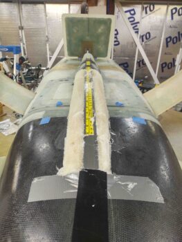
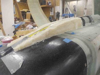
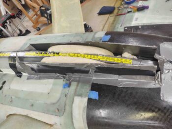
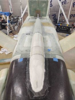
And a bit more after I pulled the taped yardstick… which defines the bottom surface outline.
A bit more focusing on the symmetry of the very aft intersection with the bottom cowling.
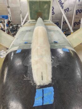
And finally I got all the foam shaped and vacuumed, ready for glass!
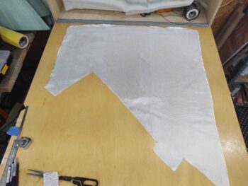
I just wanted to point out that this is all the BID I have remaining out fo the 10 yards I ordered from ACS not too long ago. I have another bunch coming in early next week. Crazy how much glass, peel ply and epoxy I’ve been burning through these past few months!
In final prep for the 2-ply BID layup I marked and cut the foam RAM air scoop aft extension structure at the hell hole hatch cover aft line and the bottom cowling forward intersection line. I’m calling the narrow area in-between the “firewall bridge.”
I then added a dry micro fillet around the edge of the foam and filled any larger areas in the foam surface requiring it.
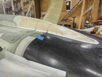
I then laid up the 2 plies of BID. Since this is just a fairing, and not a structural airframe component, I used West epoxy to save my MGS as much as possible.
Here’s a shot from the aft side. The joggle in the centerline of the bottom cowl made the very aft curve a little challenging to nail down. I’m going to have to call in some assistance from the finishing micro to dial this in exactly before paint.
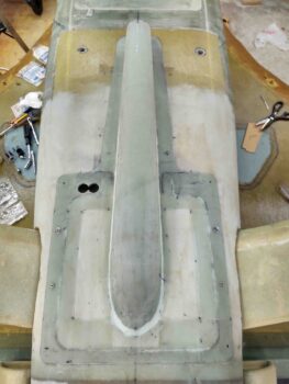
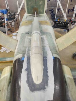
And a whole now-completed RAM air scoop structure shot.
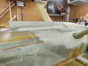
I then peel plied the layup… again, here we have a side profile shot.
And another long view shot. Yep, I used one piece of peel ply for the entire layup.
With that, I called it a night and left this layup to cure overnight.