
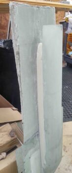
I started out today by drilling out and removing the top skin to reveal a threaded hardpoint I had placed on the centerline of the fuselage aft of the landing brake —the aft of 2 hardpoints with the other forward of the landing brake— based off a recommendation from Dale Martin, back in 2012. The idea was to allow for mounting a long strait piece of aluminum to ensure the engine, nose, etc. were centered. I never used them (maybe I should have!) but knowing that this one was available I worked it into my design for securing the RAM air scoop.
I had a boss in the Air Force that often stated, “Luck is when preparation meets opportunity.” And I feel that this hardpoint offered me a bit of luck. Why? Well, with having an internal GIB thigh support fuel sump, which led me to laying in a ply of Kevlar as a safety measure just in case I have an engine out landing that rips the gear off, and thus finds the bird sliding down asphalt on its belly, I wanted to have a protective layer to keep the fuel sump from damage in such a scenario.
All that limits my options on embedded hardpoints for securing the RAM air scoop.
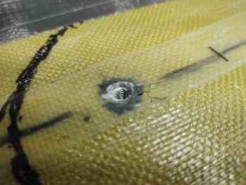
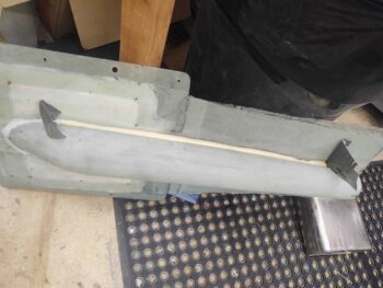
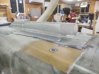
The black Sharpie line is an initial arc around the front of the RAM air scoop for determining the size of the mounting flange. Here you can see a screw in the threaded hardpoint. You can also see there is only Kevlar covered by UNI for a good bit moving aft before any added foam starts appearing.

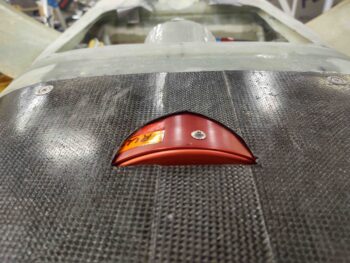
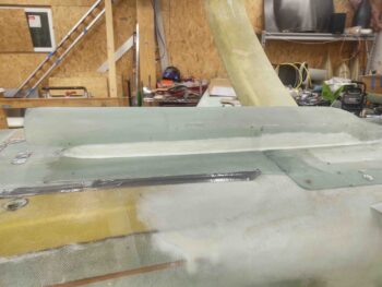
Onto the RAM air scoop mounting flange, I installed a countersunk screw into the hardpoint to make it a bit more visible. I then mounted the RAM air scoop/hell hole hatch cover.
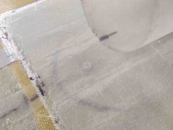
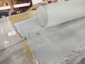
I then drilled into the center of the screw to mark the center of the hardpoint, removed the RAM air scoop, drilled out the remainder of the screw mounting hole… then mounted the RAM air scoop back into place, securing it with the new screw attach point.
I will note that my optimum design would not have a screw dead center in front of the RAM air scoop inlet, but I think the chances of a properly mounted screw coming out and going into the intake is remote. Moreover, beggars can’t be choosers!
Now lets discuss the other hardpoints along the sides of the RAM air scoop. The farthest aft, about 2-3″ forward of the original front edge of the hell hole hatch cover, will be a pair of CAMLOCs… making up 4 CAMLOCs total used on this RAM air scoop/hell hole hatch cover.
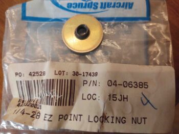
Forward of those CAMLOCs the thickness of the foam starts diminishing quickly. I was going to use K1000-3 nutplates secured to phenolic, as I normally do. But when I tested the thickness of these EZ Point locking nuts I discovered they were over a 1/16″ shallower in depth than a phenolic nutplate assembly… yes, I’m scrambling for as thin as possible to allow me to place a pair of RAM air scoop securing screws as far forward as possible. Also note these are 1/4-28 size, so I ordered a pair of 10-32 EZ Points from Aircraft Spruce.
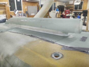
I then got busy filling in the gap that runs along the side and in between the RAM air scoop and it’s mounting base/flange. This was the initial pour, and I needed another one to finalize the fill on the side of the RAM air scoop assembly.
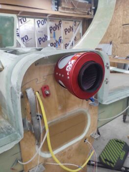
While the different rounds of pour foam cured on the RAM air scoop, I installed the RAM air can on the back of the firewall. Here it is mounted with 5 SS screws from inside the hell hole (see pic below).
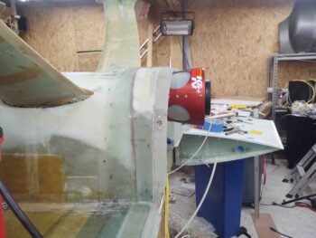
Here we have a side view showing the aft edge of the RAM air can peaking up above the horizontal line going back from the flange around the bottom of the firewall. This is even more significant given that the bottom cowl tapers up as it moves aft, so the can needs to poke through the bottom of the cowling.
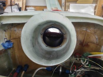
Here are the 5 SS mounting screws from the inside of the aft RAM air scoop section. And yes, I need to add to/clean up the fillet on the inside aft edge of the RAM air scoop section.
Here’s a shot of the RAM air can peaking through the bottom of the cowling.
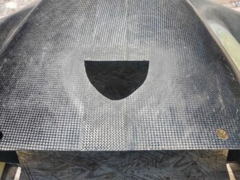
I took the bottom cowling outside and cut just a hair more of this notch to allow a scant more clearance between RAM air can and bottom cowling. I also sanded the carbon fiber surrounding this notch for glass.
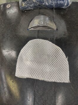
After remounting the bottom cowling, I used taped cardboard to add a little padding around the RAM air can, then cut a scrap piece of BID.
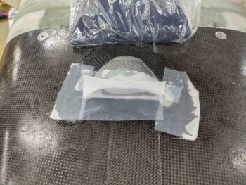
I then laid up the BID and peel plied a good bit of it. This glass will created a barrier when I later add pour foam to the bottom cowling as an aft extension of the RAM air scoop assembly.
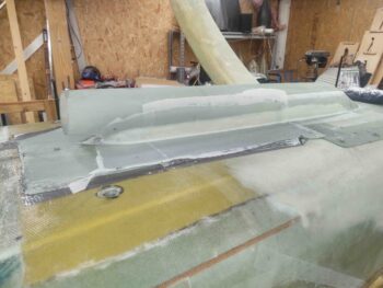
I then spent a good bit of time shaping and cleaning up the added pour foam on the RAM air scoop.
I then remounted the RAM air scoop/hell hole hatch cover back in place on the fuselage in preparation for glassing. I glassed layup #5, which is the final layup for the RAM air scoop base/mounting flange. I also laid up a strip of BID aft of layup #5 to cover the aft foam transition area.
Here are a couple more shots of these layups. Note that I peel plied all the layups.
And one final shot of peel plied layup #5.
I then called it a night and left the layups to cure overnight.