It hit me about 5am this morning that I should have pulled the protective tape after just a few hours of the landing light lens perimeter glass layup curing… but I didn’t. When I pulled up the tape there was some epoxy that had seeped up onto the lens and cured (sorry, no pic). And it of course was stubborn and didn’t want to come off easily. I tried a plastic razor blade just for this occasion (one would think!) and it did nothing.
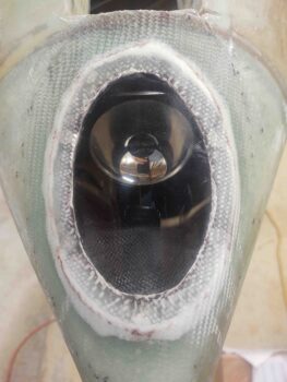
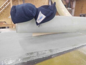
I then grabbed some white vinegar and soaked down a paper towel and let it sit for a good 5 minutes on these ugly intrusions onto my landing light lens. Then, as carefully and as lightly as I could, I used a razor blade to skim off these cured bits of epoxy. For the most part it worked a treat, although on the right side in the pic below you can see some scratches. I’m hoping those will buff out… and clearly that’s simply cosmetic and doesn’t affect the functioning of the lens or landing light in any way.
All told, this was a good hour-long endeavor.
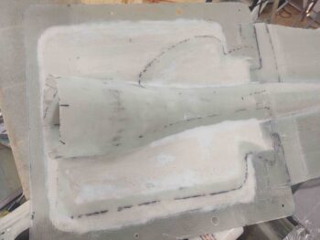
I then pulled the peel ply and cleaned up the layups on the interior side of the RAM air scoop securement to the hell hole hatch cover. Layups looked great and I’m very pleased with how they came out.
I then reset the RAM air scoop/hell hole hatch cover back in place and secured it with the CAMLOCs and screws. It fit a treat and so far it seems to be functioning exactly as I designed it and hoped it would.
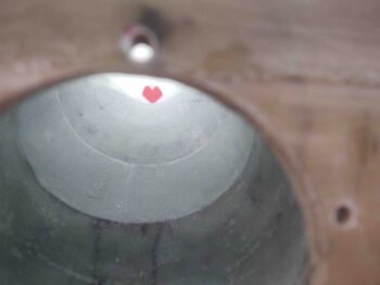
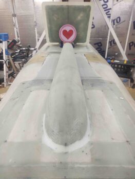
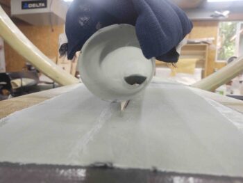
I wanted to capture the fact that even with the shallow ‘S’ curve in the RAM air scoop design, that you can see through it from one end to the other. Here I grabbed a pic of something that was fairly bright and visible —a heart candy tin from Valentine’s Day long ago, which is where I now store the LIDAR laser altimeter.
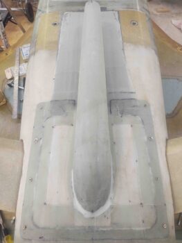
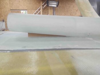
Here’s what it looks like from the topside, just FYI.
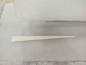
I’ve had an ongoing internal debate in my mind whether to simply use pour foam to clean up the interfacing edges of the RAM air scoop and its base, or to also add in a supporting spline —akin to what an F-16 has between engine air scoop and fuselage bottom— betwixt the two… so I cut a thin cardboard template to test it out.
I liked the way this looked and felt I could integrate it into the design. I will note that I plan to lop off 0.4″ from the front air scoop inlet so the spline won’t be set as terribly far back from the inlet opening as it is here. A bit back, yes, but not too crazy (I hope!).
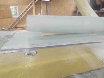
I then transferred the cardboard template to my stock of 1/16″ thick G10 phenolic and cut out the real version of the supporting/interconnecting spline. Again, with my cheap band saw it’s not perfect, but it will do (pic #1).
It then took a few iterations of test-fitting and sanding to get it to fit just right (pic #2).
I then 5-min glued the top and bottom edges of the RAM air scoop-to-base supporting/ interconnecting spline. I set it and weighed the top to maintain my 0.95″ gap between base and air scoop inlet opening.
Here’s a view of both supporting/interconnecting spline and down the chute of the RAM air scoop.
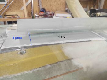
I then measured and cut 2 plies of BID. They are both opposite “L” shapes, so one like this: ⌈ and the other like this: ⌉ with the horizontal sections overlapping each other at the very forward end of the RAM air scoop base … as I’ve labeled the pic below.
Since I wanted the support base mounting flange to be 5 plies thick, this layup completes the front section of the base from the front edge of the supporting/interconnecting spline forward. I will then fill in the area from the front edge of the supporting/interconnecting spline AFT with pour foam to eliminate a good bit of intersection drag. The layup that covers that along the side will be layup/ply #5 for the side runs.
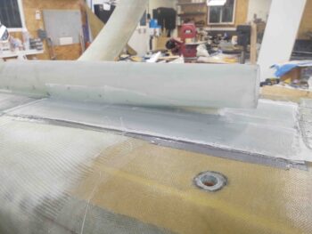
As you can see, I of course peel plied layup #4 (or #4.5 if you will).
Tonight was an early evening off as I went to dinner a bit earlier than normal and simply relaxed… I’ll be back at it hard tomorrow.

