
I started out today by cleaning up and mounting the 3D printed Fuel Injection Servo air induction tube to allow laying up the initial plies of carbon fiber, essentially turning my mocked up test part into a layup form.
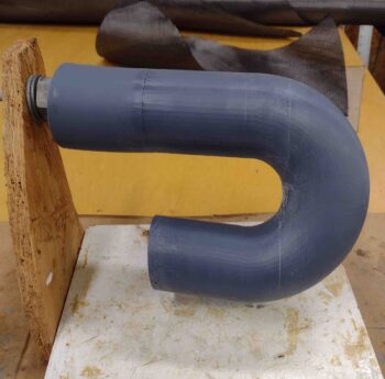
I started out by peel plying the 3D printed air induction tube first, then laying up an initial ply of carbon fiber UNI, followed by an overlapping ply of CF BID. I’ll note that all the CF BID I used on this initial layup were scrap pieces.
I then peel plied the initial carbon fiber layup on the 3D printed air induction tube plug.
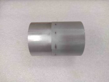
While the initial air induction tube carbon fiber layup cured, I then cut a piece of tubing —that will make up the SCEET attach point on the front end of the air induction tube— off the foot-long length of 2.5″ diameter 6061 tubing. To avoid any negative carbon fiber-on-aluminum galvanic reaction over time, I went ahead and wrapped the ~2″ part of the tube that will get attached to the front of the air induction tube with a ply of UNI, then peel plied it.
I then set aside the glassed aluminum tube to cure as well.
I grabbed one the two air induction tube mounting plate 3D-printed mockups and used it as a template to mark up my 1/16″ thick stock of G10… to create the actual mounting plate base.
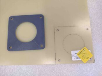
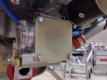
Which I did here: I cut the marked G10 stock, sanded the edges, radiused the corners, and drilled the 4 corner bolt holes. I then test fit the air induction tube-to-Fuel Injection Servo mounting plate in place on the servo. As you can see, it fit like a champ.
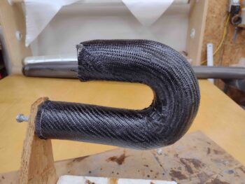
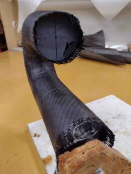
A few hours later, after the air induction tube carbon fiber layup was about fully cured, I pulled the peel ply and cleaned up the edges and surface.
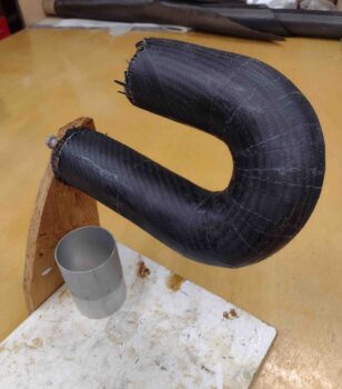
Here we have the carbon fiber layup on the right side of the air induction tube form.
And a final shot with the peel ply pulled and the carbon fiber ready for trimming on each end.
Tomorrow I’m going to an FAA A&P/IA training session (I’m neither but was invited by Alan from Precision Airmotive) so I probably won’t get much work done, if any, in the shop.
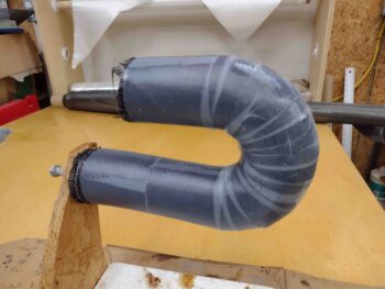
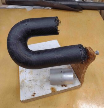
When I do get back in the shop my next step will be to trim each end of the air induction tube carbon fiber layup, sand it to smooth out any rough/high spots, and then cut it down the middle of each side to extract the internal 3D printed plug from inside, plus the internal peel ply.
I’ll then clean up any areas on the inside of the air induction tube halves that need it before floxing and glassing the halves back together. After that cures I’ll glass the top Fuel Injection Servo mounting bracket into place and add the 2.5″ diameter 6061 tube to the lower forward edge. At least that’s the plan.