
When I removed the fuel injection servo side air induction tube segment from the 3D printer plate it cracked a bit (more in some spots) and I tried the proverbial super glue to repair it. That worked on about 50% of the cracks.
Thus, to ensure no future damage and that the geometry stayed fixed as I had modeled it I taped up the tube segment to ensure it would A) stay together and B) not crack further.
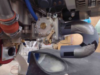
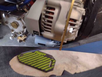
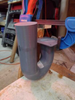
I then hot glued the tube portion to the flat mounting bracket portion. After waiting about 15 minutes to ensure the hot glue was fully cured, I mounted the entire assembly to the aft face of the fuel injection servo.
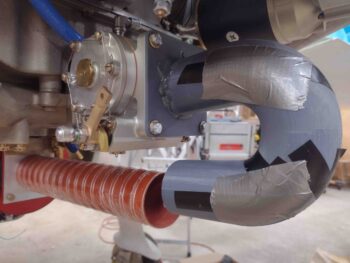
A couple more shots of the taped up and hot glued air induction tube mounted to the fuel injection servo.
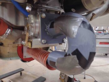
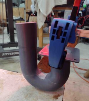
An alignment shot from the aft side… note the SCEET tubing is off to the right a bit.
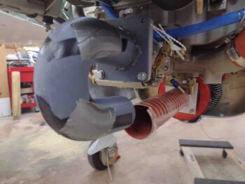
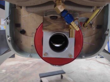
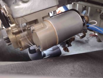
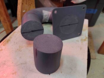
A quick shot of the RAM air can SCEET tubing attachment bracket. The wood block is to keep the adapter bracket pressed up tight against the RAM air can since I’ll need CS screws coming through the RAM air can flange going aft to secure the adapter.
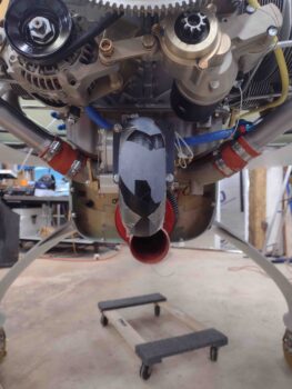
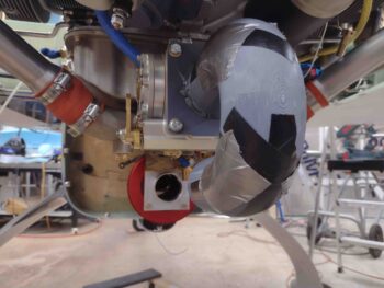
Here we have both ends of the engine area induction system: the RAM air can and the future carbon fiber 180º tube assembly on the fuel injection servo.
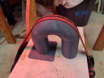
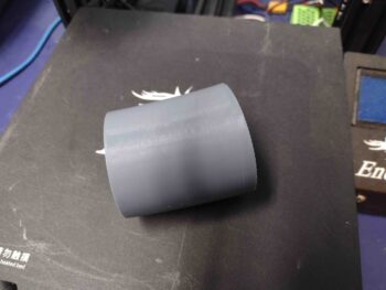
A reminder of the modeled version of the air induction tube, for discussion below:
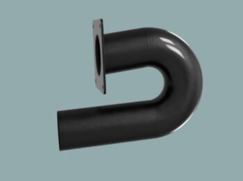
And one more side shot of the 3D printed mocked up air induction system tube.
Note how the lower forward-traveling tube below ends close to even with the start of the tube above it. This is how I needed to 3D print the major curve of the tube, but ending it short also allowed me to design a curve and flared transition to mount the segment of 2.5″ diameter 6061 tube to the front portion of this tube assembly… obviously for mounting the interconnecting SCEET tubing.
The first order of business was to re-mount the bottom cowling and check the clearance between this air induction 180º tube version and bottom inside cowling….

I’m happy to report that I reclaimed my original clearance plus a good 1/8″ or so, with over 5/16″ total clearance between tube and cowling: 0.33″ to be exact. Again, not the 1/2″ or so I would prefer, but beggars can’t be choosers and I’ll take what I can get.
With my clearance good to go, I needed to do two tasks that would take a bit of time to complete.
First, I filled the cracks on the 3D printed mockup of the air induction tube with raw epoxy, flox and micro. I then put a weighted strap over the tube to compress it all a good bit while it cured under a couple of heat lamps (it was about 38º F outside).
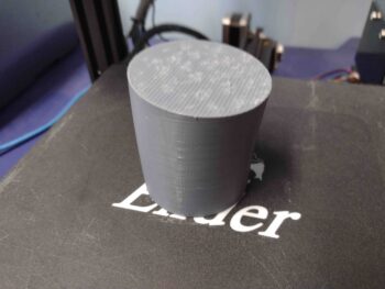
I designed the flared 5º-curved forward segment of the air induction tube, that will intersect the 2.5″ 6061 tube adapter. I then kicked off the 3D printing of it before heading out for a quick dinner… with the 3D printer working this 3 hour print while I was out.
Upon returning home from dinner, I then sanded, acetone’d and marked up each end of the tubes in prep for joining them together with flox, and a few dabs of 5-min glue . . .
Which I did here. After pressing the parts together by hand for a few minutes, and ensuring they were aligned correctly, I then clamped the assembly in place to let gravity do its job.
Here’s another shot of the flared (2.3″ aft intersection to 2.4+” forward <top> face) 5º tube extension flox attached to the front end of the 180º tube assembly.
Tomorrow will be a busy day socially, but I at least want to get the carbon fiber cut for the layup to get this 180º air induction tube assembly glassed/constructed.