
Today was all about working the Fuel Injection Servo air induction tube initial carbon fiber layup. As an aside, yesterday I discussed my plan and showed pics of my configuration to Alan Jesmer from Precision Airmotive, to which he noted that he didn’t see any issues with what I had in mind for implementing my air induction system.
I started off by using my Fein saw to trim each end of the air induction tube. I then sanded the edges of each end.
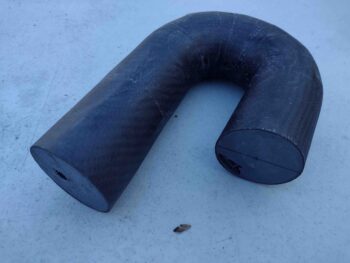
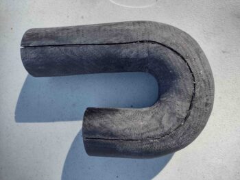
I then spent a good bit of time thoroughly sanding the exterior surface of the air induction tube initial carbon fiber layup.
I say “initial” carbon fiber layup since I need to split the current tube into 2 halves to first extract the 3D printed plug and internal peel ply, and then sand and prep the internal surface to ensure the air gets as smooth of a ride as possible on its way to the FI servo.
Then I’ll layup at least 2 plies of carbon fiber along the seams when I create a single tube again… one ply which will encompass the entire exterior surface of the air induction tube. Obviously these last layups will be the “final” carbon fiber layups.
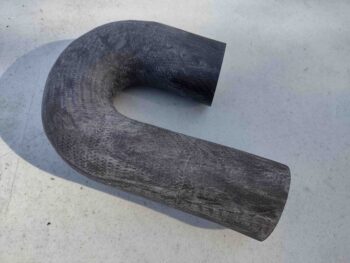
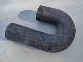
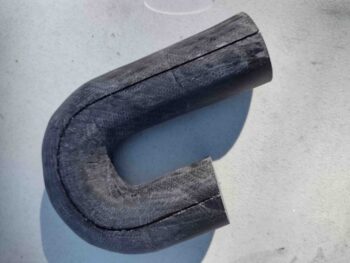
Here I marked a cut line on both sides of the air induction tube. The reason I’m cutting horizontally along the sides vs vertically down the middle (which I would prefer) is simply to keep the buildup of composite material at a minimum along the bottom center of the tube, which is of course the area that is closest to the inside of the bottom cowling… with the least amount of clearance with said cowling.
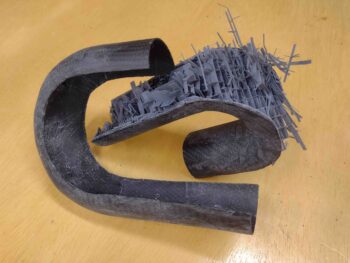
I again used the Fein saw to cut down the marked cut lines to split the carbon fiber tube.
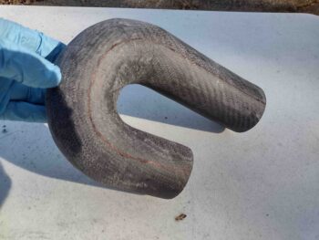
Of course I still had a pretty much intact 3D printed tube mockup/plug on the inside that I had to pry apart. After a good 10 minutes and some judicious destruction, with prejudice (ha!), the 2 tube halves finally came apart.
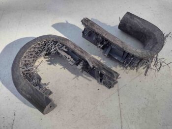
I then spent well over an hour prying out both the plastic and peel ply from the inside surface of the outer portion of the tube. You can obviously see the 3D print innards on the other half of the tube….
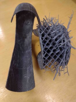
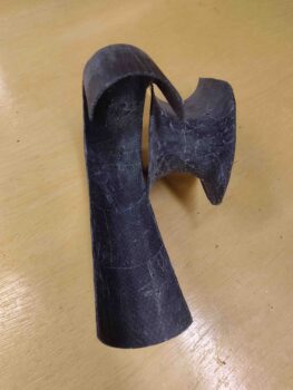
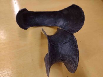
Which I then tackled next. It was a little easier than the first half of the tube since it’s essentially an outside curve and I had much more access to get in and remove the plastic and peel ply. Plus, since it’s the inside of the curve, there is simply a lot less surface area. That all being said, it still took nearly an hour to extract all the plastic and peel ply from this side of the tube as well.
I had planned on doing a bit more, but I had promised Jess that I would spend an early evening and dinner in New Bern with her, since it was such an uncharacteristically warm day (Yes, SHE is clearly to blame! ha).
Tomorrow I’ll give the inside tube surfaces a good sanding and then fill the holes/depressions with a micro/West 410 mix. After that cures and I sand the micro fill, I then plan on doing at least a couple epoxy wipes to help fill in any leftover holes, gaps and low spots. Plus I would simply like to have the inside of this tube as smooth as possible. After the inside tube surface prep is complete, I’ll then rejoin the tube halves and finish constructing the air induction tube.