
Today was yet again one of those long days with seemingly little to show for it at the end of it.
Still a lot of sorting through wires to optimize their routing and flow, picking off the low hanging fruit that were easier to route and terminate into their final end points. That being said, my primary targets today were the E-Bus, the G4 Ground Bus and the Main Bus.
The E-Bus got two new entrants into the club, with the power wire that feeds the HXr and AHRS primary power connections via the panel mounted “avionics” switch getting connected to the top fuse buss threaded stud. Again, since GRT recommends fusing on power feeds AFTER a switch, the fuses for both the HXr and AHRS are inline fuses, with the power feed wire again going straight to the E-Bus threaded stud… no need to waste a fuse slot.
The switch on the panel that sits immediately inboard of the HXr & AHRS Master switch is the belly RAM air scoop open/close switch. The power wire for this switch routes in a bundle horizontally across the top of the E-Bus and then terminates into a fuse position low on the front side of the E-Bus (left side in pic). It’s targeted fuse tab was F06, with F07 being the bottom fuse position on the forward side.
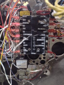 However, the wire was about 2″ too short to be routed properly AND reach the F06 fuse position, so I swapped it with the currently open F04 fuse spot which is/was for the transponder (wire not ran yet). Again, that meant some relabeling [I printed off and applied about ten labels today], fuse position swapping and document updating. Moreover, the RAM air switch power also shares its fuse with the gas tanks’ fuel level probes and power to the GIB headrest avionics bay cooling fans.
A minor issue I ran into was that the white/orange striped wires from both 6-wire cable #1 and #2 that feed the fuel probes and cooling fans, respectively, were also not long enough to reach the E-Bus fuse tab, even after the swap. With no white/orange wire on hand, I spliced a length of an orange wire and an orange/black wire in the FastOn connector to later connect/splice to the white/orange wires from the two 6-wire cables (which I plan to do tomorrow).
In other news… I then found and retrieved out of the bundle the two main wires that connect up to the B&C Voltage Regulator: the F-Lead from the L-40 alternator and the power lead from “ALT FLD” circuit breaker via the Master Switch. As par usual (ha!) the F-lead wire was about a foot too short, so I spliced a length of white 20 AWG wire to the existing F-lead.
Here we have the B&C Voltage Regulator wired and installed.
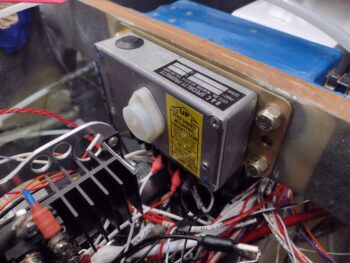 I’ll note that BEFORE I installed the voltage regulator I spent over an hour reorganizing, consolidating (via piggyback FastOns) and re-terminating the G4 ground wires to move them all to the forward 2 of the 4 vertical rows of tabs, starting from the very top and moving down.
I also terminated and connected up a few more loose ground wires during this process, like the un-terminated piggy-back ground wire hanging free at the bottom of the pic above. Once I terminate another ground wire I’ll connect the two and install them as a single unit onto the G4 ground buss.
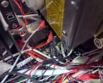 If you look directly below the voltage regulator’s yellow label you can make out the open tabs on the G4 ground buss. The reason for my reorganization on the G4 ground buss was simply for “easier” (as much as possible) access to install ground wires with the voltage regulator installed.
Thankfully, once the ground wires are connected in this out of the way corner, I expect to have to get in there very rarely, if it all, once the bird is flying. I’ll further note that the main impediment to easy access to the ground buss tabs is a combination of the wire bundle coming from the nose and the nose hatch latch cable.
So the total for today was 4 ground wires terminated and installed on the G4 Ground Bus, a couple wires added to the E-Bus, a couple more terminated on the main bus and the CABIN HT indicator light power wire soldered into place.
And with that… pressing forward!