
Another 2 day update here, and I have to admit that it’s hard to remember and recount all of the single wires that I’ve ran, spliced and/or terminated.
I did do the final connect on all the Garmin GNS-480 power and ground wires. The thick green marker lines are how I’ve been denoting that wires are run and connected on the different wiring diagrams.
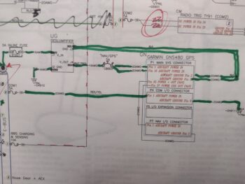 Now, see that chicken scratching at the top of the diagram? I’d like to be able to print out new 11×17 inch diagrams but my Brother printer is not doing well and needs some rehabilitative TLC to get back online for printing… which of course takes time. To add to my tale of woe, after printing out most of the GNS-480 Installation Manual on my regular Canon printer, 2 days later I get an error code that essentially said that barring a few YouTube hacks, I need a new printer head… which I pulled the trigger for on Amazon.
This is just all to say that I’ve spent well over 3 hours over these past 2 days just messing around and learning about printer operation issues!
I did solder splice the orange and orange/black wires from the E-Bus fuse tab F05 to the the white/orange wires in the respective 6-wire cables coming from the GIB headrest and Hell hole (no pic of that).
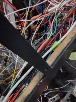
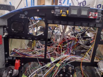
Also out of the 6-wire #2 I found the white/green and green wire pair that powers the RAM air valve open and close, via switch 16 (left side of panel). In the pic below this pair —now spliced to the switch wires— travels from lower left to upper right. And yes, the remaining wires are still a crazy rats nest… I’ll need to run around 20-30 wires before I can start making any real attempt at wire/cable management.
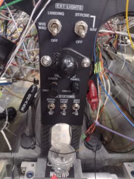
 Since I moved the power source to the Pitch Trim module to the Battery Buss (from the Main/Master Buss) I had yet another splice job to tie the new power wire coming from the nose area to the existing (albeit shorter) power wire coming off the switch. I then did the final install of the Pitch Trim Master power switch (lower left switch in pic).
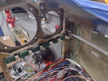
 Over the next couple of hours I worked on getting the Warning Annunciator Sub-Panel installed, with the wires passed through the panel for their final connections (shown after below pic).
I then finalized the colors and positions of the GNS-480 annunciation lights and affixed them in place with a dollop of hot glue on each outer edge of every light. The lights sit in the their openings fairly snugly already, so the glue was just to ensure they don’t vibrate out.
I then prepped and added tubing to the alternate static source switch that is positioned about as close to the left sidewall as you can get. I then mounted the switch hardware to finish off the install.
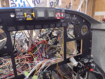
 With the alternate static switch installed, that then allowed me to install the MiniUni-2 backup EFIS & fuel timer into the outboard top left instrument position. In addition, I installed the AP SRC (aka “Autopilot Source”) switch just above this backup EFIS. Of course note that the Warning Annunciator Sub-panel is installed at the top center of the panel.
 Again, here we have another shot of the installed Warning Annunciator Sub-panel, as well as the freshly installed Vertical Compass Card on the right outboard top instrument position. I’ll note that other than SW011, the Pitch Trim Master power switch, none of these other just-installed components’ wiring is complete yet.
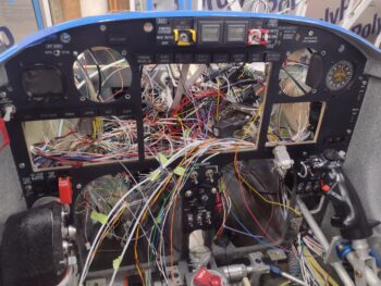
 And a parting shot with all the newly installed instrument panel tidbits in place. I expect to spend another 2 days simply wrangling and bedding down more stray wires, as I have been, before I start in on installing any other panel components. As I mentioned in my last post, I also need to set a good bit of time aside to install/wire the Intercom as well.
 Pressing forward!