
This post covers the past couple of days.
First off, I ordered another stylus for my Centroid Acorn CNC probe. Centroid has a program where you can send your probe back into them for calibration and even replacement if needed, but it’s a one time event in the life of the probe and you still have to replace any missing stylus. Since my tolerances aren’t (read: can’t be) super tight on this current mill, I just ordered a new stylus.
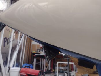
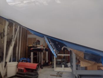
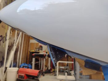
As promised, here is a shot of Taxi Light pivot arm #7 (pic 1), with pivot arm #6 (pic 2) and pivot arm #5 (pic 3) added for comparison. Clearly I need a runoff between #7 and #5 to see which final version will get installed currently… again, with plans to tweak the geometry after the bird’s in the air.
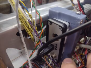
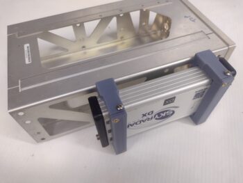
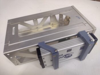
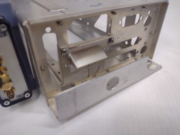
In poking around in the remaining panel areas that still yet need to get populated, I stumbled upon a clearance issue between the SkyRadar ADS-B IN receiver’s aft bracket and 2 of the 3 connectors on the backside (technically front) of the HXr. The HXr frame will clear the actual SkyRadar unit but its protruding D-Sub connectors will not clear the mounting bracket.
Also note the USB cable off the SkyRadar unit, which is 3 feet long. The USB hub that it connects to is 6″ away. So I ordered a new 9″ cable with a 90° mini USB connector that will mount into the SkyRadar aft face… again to optimize clearance with the HXr.
 I spent nearly an hour in CAD modeling up a new bracket that is simply a 45° version of the current retaining bracket. Clearly the bracket is mounted away from the HXr, which SHOULD provide clearance for the HXr’s D-Sub connectors. My last task of the evening of Day 1 was kicking off the 3D print of this guy, which took about 2.5 hours.
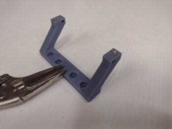 This morning I staked a pair of brass threaded inserts into the SkyRadar’s new angled mounting bracket before taking it out to the shop for install.
As a reminder, here is the original pair of brackets (pic 1). And here is the GNS-480 mounting tube with the SkyRadar ADS-B IN receiver’s new 45° foward-biased bracket (pic 2).
I then got busy machining the “aft” angled bracket of the GNS-480 tube that will help wrangle and secure all the wires and cables connecting to the GNS-480.
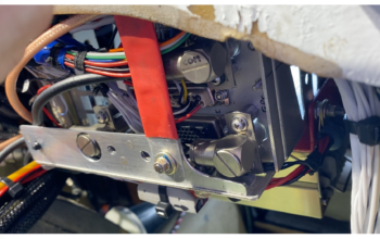
As a reminder, this is a close copy to what Marco has on the “aft” side of his GNS-480. Note the red support arm that is bolted to this bracket and to the aft side of the F28 bulkhead. This is probably the most important feature of this bracket and, if you remember, I already installed a Clickbond on the aft side of F28 just for this purpose.
 Here I’m machining the vertical wall of the angled 6061 aluminum to create this bracket.
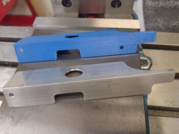
And here is the finished machining of the vertical wall of the bracket. I put the 3D printed model in the shot for comparison of 3D model vs machined part.
 But wait just a darn minute you state emphatically!
“Didn’t you crash and destroy the stylus of your probe?” — Yes.
“Didn’t you have to order a new one?” — Yes.
“I guess you’re finding Z0/X0/Y0 via ol’ skool machining methods then?” — Hell no!
“Then what in tar-nation is going on?!”
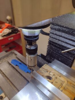
Interestingly enough, Centroid has the dimensions and threads of the probe stylus listed on their website. Again, since my tolerances aren’t critical for this part, I simply modeled up and 3D printed a stylus to get this job done, and pressed forward. Improvise, adapt and overcome!
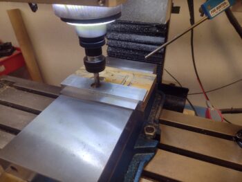
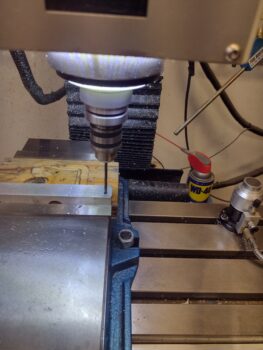
Here I’m using the 3D printed stylus to determine zero for all axes before machining the bottom of the GNS-480 bracket.
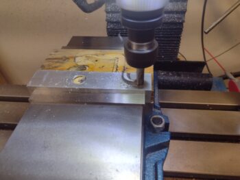
 Although there are 2 screw mounting holes in the bottom of the bracket to mount it to the GNS-480 tube, I only used the mill to drill one of them. After I secure the bracket to the GNS-480 tube I’ll drill the other hole to ensure they are spaced just right to line up with the pre-existing holes on the tube flange.
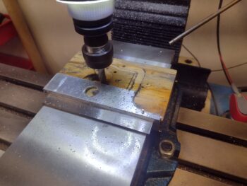
 I then machined the bottom bracket angle leg using a 3/16″ 2-flute end mill (pic 1). Again, here is the machined angle bracket pictured with the 3D printed model (pic 2).
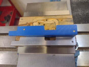
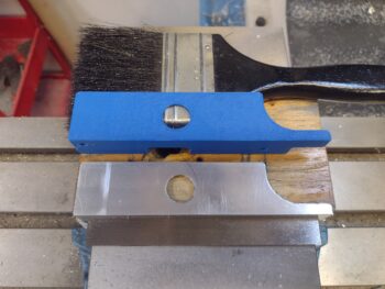
And one last shot of the machined GNS-480 mounting tube bracket and the 3D printed model.
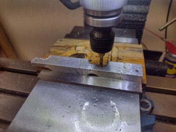
 Using the single bottom mounting hole I then attached the bracket to the GNS-480 tube with a #6 screw. With the single screw in place and using a clamp to secure the bracket, I then drilled the other screw hole and installed the 2nd screw.
Tomorrow I need to attach a #6 platenut for each screw, but before I do that I’m going to assess whether I should machine some zip-tie slots along the top edge of the bracket… in the same manner I machined the zip-tie slots on the GPS puck plate.
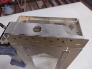
Here is the GNS-480 tube with the bracket temporarily secured with a pair of #6 screws.
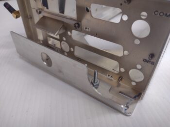
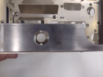
 And this shot shows the where the 90° antenna cable connector is mounted to the actual GNS-480 tube back plate, and the large hole in the bracket that provides clearance for that antenna connector. On the lower right side in this pic is another 90° antenna cable connector which is why there is a large scalloped portion removed from the bracket [there is also a third 90° antenna cable connector in the upper right of the pic, which clearly has no clearance issues with this bracket].
 Tomorrow I plan on finishing the install of this bracket, including making and installing the support arm from F28 to the bracket. Part of the GPS navigator install prep will be firing up the GNS-480 in its simulator station to ensure all is good with it before I mount it into the panel. I will also work to finish up the Taxi Light pivot arm install in my quest to get the nose battery compartment squared away and ready for operations.
Pressing forward!