
Yes, I plasma cut the GPS antenna puck plate yesterday and then machined the slots for the zip ties today.
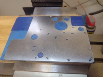
I had an unfortunate (and costly) incident while machining this part: my mill drawbar is getting old and sticks a bit, often needing a sharp rap to free the tool in the spindle. Well, in that process I lost control of the probe and it crashed into the upper left corner of the part below, shattering the stylus on the probe. Nothing that $100 and another round of dialing in and configuring a new probe won’t take care of (sigh).
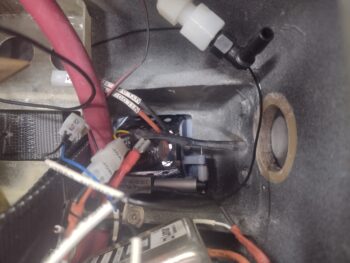
Regardless of my woes, the show must go on. Here we have the puck plate ready to install.
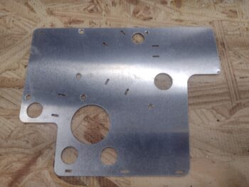
Since I won’t have the required access after the puck plate is installed, I went ahead and preinserted the zip-ties in prep for securing the GPS pucks’ wiring bundles.
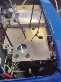
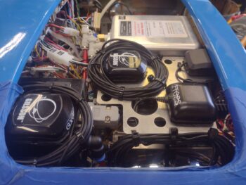
I then finished physically installing both the puck plate and 3 GPS pucks atop of it (HXr/ AHRS, TruTrak ADI, and MiniUni2 Mini-EFIS). As you can see, all the copious amounts of included cabling has been wrangled, or in the case of forwardmost MiniUni2 GPS puck the cable is routed over to the left side of the avionics bay via the aft side of the F28 bulkhead.
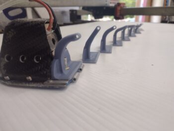
I then continued on in my quest to find the most reasonable configuration for the Taxi Light pivot arm, with pivot arm #6 making its debut.
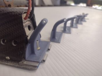
And here is pivot arm #6 in the up/closed position.
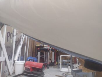
And also some exterior shots of it in the closed position (pic 1) and the open position (pic 2). Again, at this point the closed position is more critical to get this bird in the air than the open position.
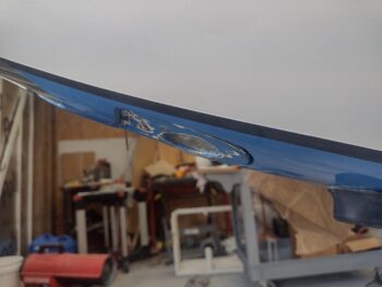
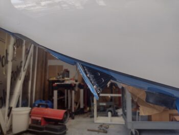
That being said, you can see the angle of the open light —which should be close to parallel with the ground— pointing downward a good bit… as in not stellar open fashion.
Thus after some assessment, I introduced a significant configuration change with pivot arm #7 to hopefully optimize both the open and closed taxi light positions. . .
Which works pretty darn well in the closed position. Open position?
Doh! Apparently I didn’t grab a pic. I’ll include a pic in my next post and discuss.
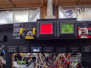
I almost forgot to show that yet another indicator light is working as designed, with the TAXI LT on light firing up when the taxi light is deployed out of the nose.
I’ll also note that after a couple of discussions with the “WiFi Expert” cable gurus out of Valencia, California, I pulled the trigger on the 2 ADS-B IN receiver antenna cables, as well as the pigtails for the GNS-480 connections to the VOR/LOC antenna (in the canard), COM 1 radio antenna, and GPS antenna puck (top of pilot headrest).
I’ll continue to press forward in these extended wrap-up actions to get the electrical system, components and panel instruments installed and operational.