
Although there are a myriad of pics here regarding the slow design convergence towards the final Taxi Light pivot arm design, there is a video at the end of this blog post showing the plasma cutting of the GPS antenna “puck plate”… for mounting the plethora of GPS antenna pucks I have on hand.
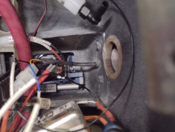
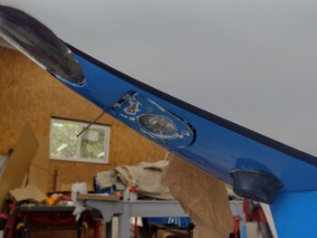
That being said, here is the inside of the nose with the Taxi Light assembly in the up/ closed position with pivot arm #3 just before I removed it.
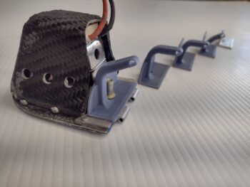
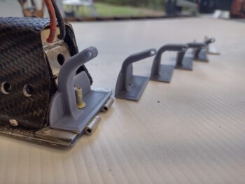
And this would be version #4. Notice how each version keeps getting taller?
And here is version #4 shown deployed from the inside of the nose. I’m not fully securing the pivot arm with a nut just yet to keep from breaking anything during my assessments.
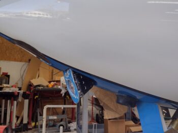
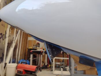
And here is how pivot arm #4 looks from the outside. The not-quite-so-closed position in pic 2 is not necessarily the pivot arm’s fault, as the sides of the taxi light assembly are catching on the inside sides of the nose opening. Some clearance-creation actions may be required.
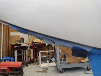
And pivot arm #4 in the closed/up position.
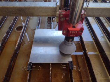
While taxi light pivot arm #5 was 3D printing, I filled up the plasma cutting table’s water tray and aligned/secured the 0.032″ 6061 aluminum plate to be cut. I also hauled my laptop computer out to the shop to run this operation.
And here we have pivot arm #5 just installed onto the taxi light assembly. Again, the trend is that they keep getting taller.
And that pivot arm height is simply to drive the taxi light as vertical in the open position, parallel to WL 0, as possible (pic 1). That being said, right now my primary concern is with the taxi light assembly fully closing and remaining secure in the nose during flight ops (pic 2). I can always tweak the geometry more fully later, but will continue to do so as long as I see obvious tweaks that can be made now.
And here is pivot arm #5 from inside the nose, with it pretty much in the fully closed position.
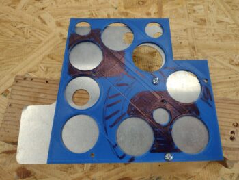
I then plasma cut the GPS antenna puck mounting plate (AKA “puck plate’) and grabbed a short (yes, actually short!) video of that process.
After quickly deburring the edges and removing a few bits of very minimal dross, I then used the initial puck plate 3D printed mockup to drill the 2x 4-40 screw holes in the plate, as those are too small in diameter to plasma cut.
I also tweaked the Taxi Light pivot arm to make version #6 and kicked off the 3D print of that, which I’ll test out tomorrow.
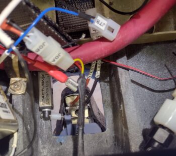
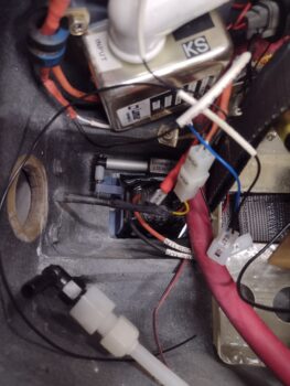
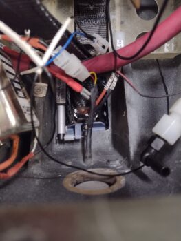
In addition, I’m happy to report that the IBBS charged up to 13.7 volts, with 13.5 volts being the bottom threshold for the unit to be called operationally ready.
Still pushing!