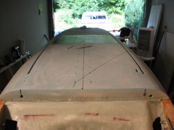
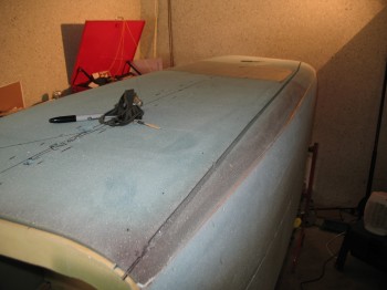
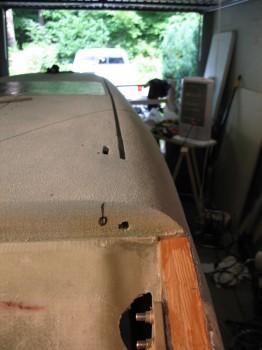
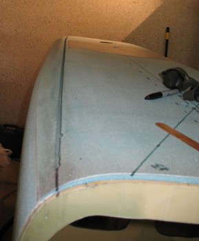
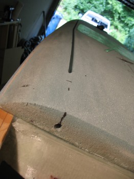
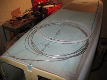
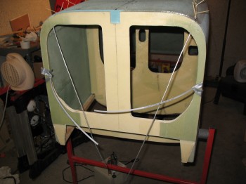
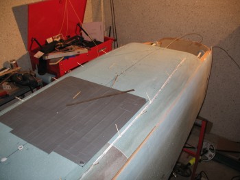
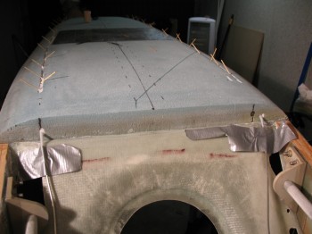
In the same fashion as the rudder cable conduit channels on the sides of the fuselage, I Dremelled a channel down each side of the underside of the fuselage, left & right of the Landing Brake, to run the brake lines internal to the fuselage glass & foam. This is another significant departure from the plans since the brake lines aren’t normally installed until chapter 15, but for all the reasons I spelled out earlier I wanted to get this mod knocked out.
Also, just as a quick mention, the plans still spell out how to install the master brake cylinders on the Firewall in the engine compartment. Ever since Debbie Iwatate’s groundbreaking mod back in 1982’ish to move the master brake cylinders forward to the rudder pedals, it doesn’t seem like there are too many builders who still mount them in back.
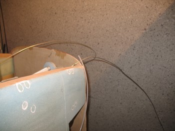
After using the Dremel to rout the two channels on the fuselage bottom, I used the #10 long drill bit (again) to drill holes at the front side of the fuselage and at the aft end of the fuselage to bring the brake lines back into the cockpit.
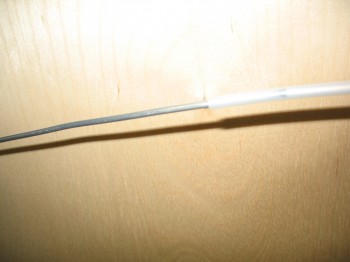
For each side, I took a 14 ft length of 1/8″ 3003-0 Aluminum tubing and inserted it into 88″ of a 3/16″ Nylaflow sleeve. Approximately 22″ of the aluminum tubing will stick out of the front the fuselage on each side.
About 1″ of the tubing, on initial entry to the interior fuselage, coming in from the exterior side of the fuselage is covered in Nylaflow as well.
After I got everything set, I micro’d the Nylaflow/aluminum tubing into the channels on both sides of the fuselage and secured the conduits in place with toothpicks.
After about 8 hours I pulled out the toothpicks. The brake line conduits looked good and were secured nicely down into the bottom of each channel.
Chapter 8 Step 6 – Installing Seatbelt Brackets
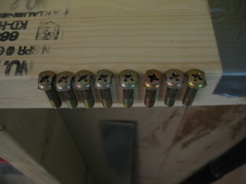
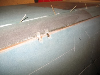
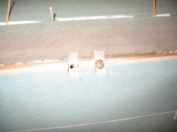
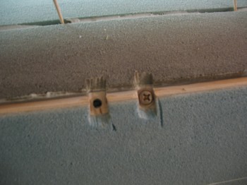
On to seatbelts! In yet another discussion with Dale Martin, he cautioned me that long before the click-bond era, many a imbedded bolt and screw would either vibrate out of the their flox mooring, or simply break loose when either being tightened or during nut removal. So, how do we ensure this doesn’t happen? Well, we make the screw head NOT round and give it an edge… for flox to grip, and provide a physical stop that prevents the screw head from turning. I ended up following his advice after even further discussing with him and a few other gurus on the affect that “butterflying” the screw heads would have on the strength of the screw. As I suspected, seems that these AN guys are pretty darn stout and it wasn’t a significant limiting factor, so I notched my screw heads in “butterfly” fashion.
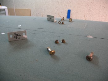
I cut 4 pairs of countersink notches into the outside corners of the fuselage around the screw holes that I had drilled previously from inside the fuselage going out, having used the seatbelt brackets themselves as a template (that’s why each bracket is marked as to where it needs to go exactly since they were initially all hand drilled and have some slight variances in hole locations, drill angles, etc). Besides just making these countersink notches just wide enough for each respective screw head to fit, I also had to make them deep enough so that there would be enough of each screw’s thread coming through the bracket to put a nut onto, and have the requisite 2-minimum threads showing after the nut is mounted.
Finally, I floxed in the seatbelt bracket screws from the outside of the fuselage inward, and put a thin film of flox on the bottom face of the seatbelt brackets. I then bolted on all the seatbelt brackets (my buddy Kevin helped by keeping the screws from spinning on the outside of the fuselage while I installed the nuts from the inside).

