
Today I made the 2 canard antennas that will be mounted under the top skin. I’m using the antenna kit from RST Engineering and following the guidance & instructions of Jim Weir.
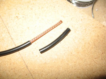
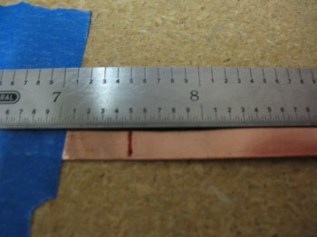
I made the VOR antenna first, with each leg (or “ear”) of the dipole measuring 22.8 inches in length. I’m also using 50 Ohm RG-58 stranded antenna cable.
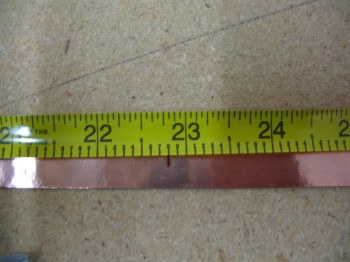
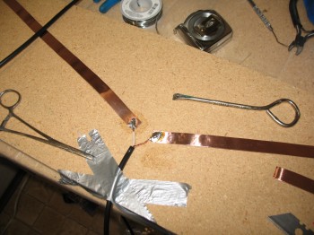
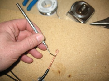
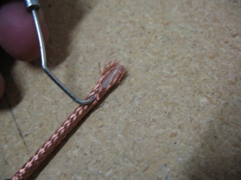
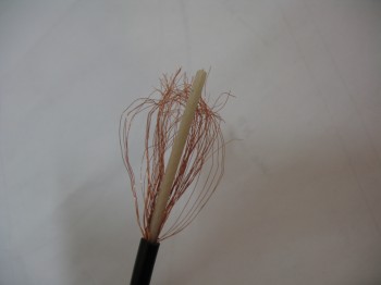
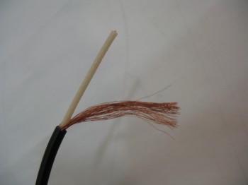
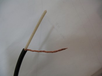
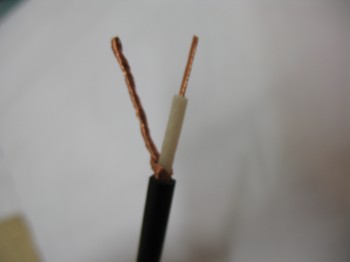
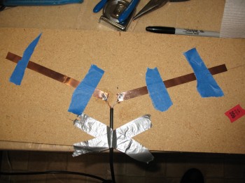
The following pictures show the general steps I take to make an antenna using Jim Weir’s design. I will say that going back and reviewing the instructions on how to make these antennas, I should have probably cut the leads a little shorter that attach to the copper foil. Of course I think the antennas will still work fine, they’re probably just not as optimized as they should be for Tx & Rx.
 I made the ILS antenna next, with dipole legs measuring 7.5 inches.
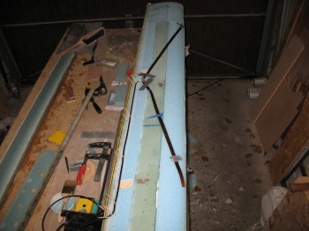
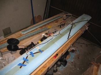
 I then mocked it up on the canard as well to figure out the best placement for both the VOR & ILS antennas.
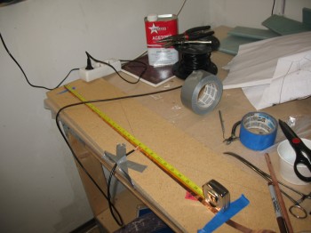
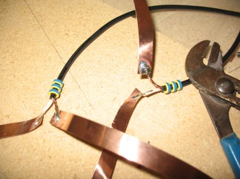
 The picture below shows the 3 Ferrite Toroids that are placed on the RG-58 Antenna cable close to the dipoles on about a 1/4″ spacing. The ferrite toroids strip off any reflected power from the antenna (technically the outside of the coax braid) before it can get into the electrical system. Using 3 ferrites eliminates about 99.9% of the reflected signal.
 These 2 antennas make up the last of the copper foil antennas that will get embedded into the skin of the flying surfaces. Here is a summary of all my copper foil antennas:
COM1 – Left Upper Winglet
COM2 – Right Upper Winglet
VOR1 – Left Wing
VOR2 – Canard
ILS – Canard
FM Radio – Right Wing