
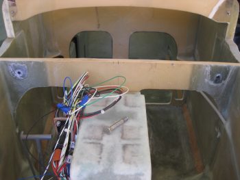
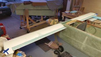
Below is the final results of yesterday’s efforts. As you can see, the spacer pads are in place for the canard lift tabs.
You’ll quite often here me refer to the “sins of the past” in regards to the build coming back to haunt me in various ways. Although, there’s an often number of times where a “mistake” turns out to actually be serendipitous in that it’s better for my specific build or better meets my requirements. Case in point is when I cut the GIB seatback Spruce hard point LWX at the plans 35° on my saw, which in reality should have been 55° on my saw for a more acute angle. When I lined everything up on the numbers, this is what created that small 0.15″ gap between the fuselage sidewall foam (underneath the CS spar) and LWY when I was mounting the canard. It also resulted in there being a slight gap betwixt the GIB seat back and the face of the CS spar. No worries though, since I actually want my GIB sitting more upright, and although this is a very minor difference in angles, the seat back is slightly more vertical than before.
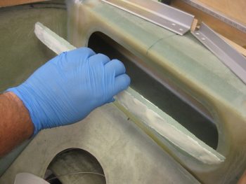
Of course now I have a gap I have to contend with. Again, no worries. I just grabbed a long thin scrap piece of Divinycell foam and sanded to shape to fit in the channel between top seat back and the lower face of the CS Spar.
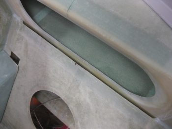
I then whipped up some micro and micro’d it in place.
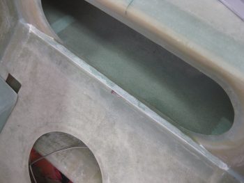
Then let it cure. There is actually a secondary gap between the aft side of the foam filler piece and the dip inward of the glass on the bottom edge of the race-track looking hole in the front of the CS Spar. Again, I think this might turn out better since that edge can be a bit of a snake pit just waiting to bite unsuspecting forearms as your leaning forward, a bit off-balance either trying to stuff stuff into the spar for storage, or when holding a wrench while mounting the inboard wing attach bolt. Thus, I will fill in the secondary channel with pour foam and then shape a smooth bull-nose type transition in prep for 2-plies of BID.
With the seat/CS spar spacer micro’d in and curing, I then set my sights on getting the elevators mounted to the canard with the canard mounted in place. I started with the right side elevator, first checking the stainless steel hinge pin alignment to see why it was so incredibly difficult to get the hinge pin reinserted when mounting the elevator to the canard. My investigation proved fruitful in that I reconfirmed that my NC2 hinge brackets are very closely aligned, with the center NC2 being maybe 0.050″ higher than the other two. The big issue was the hole in the canard swoosh tip. It was misaligned with the very first, outboard NC2 hinge bracket and was causing a fair amount of friction & discontent. Once I straightened out that outermost hinge pin hole in the canard swoosh tip, I really had a much easier time getting the elevator mounted.
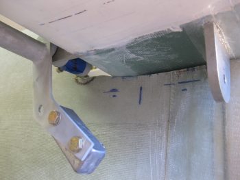
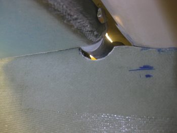
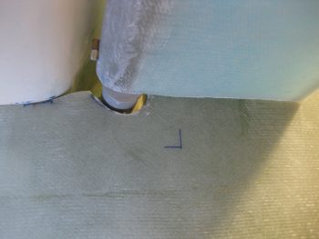
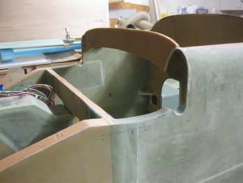
I then set the canard with the right elevator attached onto the canard mounting “shelf” of the fuselage, but since the elevator offset actuator prevented the canard from seating onto the canard mounting shelf, I had to offset it so that the right lift tab was outboard of the right side fuselage (see pic below). Understandable of course since my exact goal here was to get the rounded notch created in the fuselage sidewall specifically for the portion of the torque tube offset that will traverse from outside fuselage to inside. This portion is the tube on the very upper left side of the pic below. Since it was a couple inches away from the fuselage, I used my straight edged ruler and estimated the perimeter of the half-moon depression I needed to make on the fuselage’s canard mounting “shelf”, while of course adding in the extra 0.1″ spacing around the traversing tube as per plans.
[You may have noted that my CS11 weight is mounted a bit askew. I’ll fix that later.]
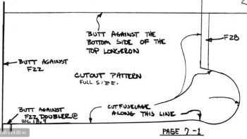
I then moved the canard out of the way in prep of creating this small notch/depression in the fuselage sidewall. I would like to point out that if you had ever wondered why I didn’t notch my top forward fuselage area as it shows in the plans (below) –with a much larger circular notch for the stock elevator torque tube configuration– it’s because with the Cozy-style torque tube offsets I knew that not much more sidewall beyond the canard “shelf” would need to be removed, which is of course exactly the case here.
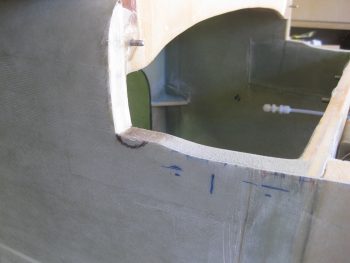
I then used my “Fein” saw, razor knife and a round Perma-a-grit tool to create the clearance required in the sidewall for the right torque tube offset.
I set the canard & elevator back in place to see that I had plenty of clearance.
The fit between the inboard edge of the elevator needed trimming for the elevator to travel full up (but not full down), so I trimmed ‘er up. As for the elevator-to-sidewall clearance spacing, the torque tube offsets are engineered so that the elevator torque tube attaches to the torque tube offset on the external side of the fuselage. Naturally, there is a bit more space required as compared to the original Long-EZ plans method of mounting the torque tube actuators internal to the fuselage. In short, this means dialing in a 1/16″ gap between fuselage and the inboard edge of the elevator is difficult at best. My estimation is that it will end up being around a 1/8″ to 5/32″ gap when the plane is finished and flying. No big deal, just a sideline affect of using the torque tube offsets.
In addition, the gap between the inboard edge of the elevator and the fuselage is really clearance measured when the elevator’s TE is at its uppermost position. As you can see, the lower the TE of the elevator goes, the gap between inboard elevator and fuselage sidewall naturally gets wider (at least it does on this bird).
After taking the same steps on checking out the hinge pin on the left elevator, I then repeated the process of creating a rounded notch for the elevator torque tube offset on the left side of the fuselage.
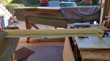
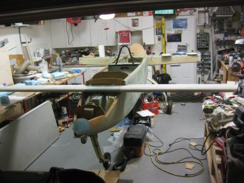
Here’s a money shot with both elevators attached to the mounted canard! A first for this bird!
Here’s the torque tube offset clearance on the left side.
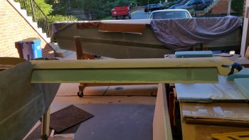
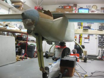
Here’s a low angle shot that I took of the mounted elevators.
And a higher angle shot (excuse the mess, but there’s an airplane being built here! ha!)
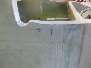
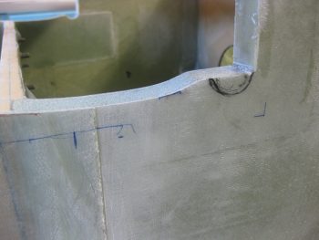
And a shot of today’s work. Not much material removed at all (thankfully!) and I’m very pleased with how little fuselage sidewall had to be removed for the offset actuators to fit into place.
Tomorrow I’ll continue my work on the elevators and the GIB seat back-to-CS spar intersection.